|
Joseph
Tarango |
|
Home |
Lab 5 : The MicroBlaze ProcessorFrom the previous labs you know FPGAs contain a reconfigurable fabric and we can reconfigure them to any RTL design we want. In this lab, we will create an embedded processor and interface it with custom hardware. The embedded processor we are going to use is called MicroBlaze and it is a complete 32-bit Harvard Reduced Instruction Set Computing (RISC) processor developed by Xilinx and optimized for FPGAs. Tentative processors, such as MicroBlaze, are known as being soft processors (another is Simple Scalar), whereas an actual chip (Intel Core i7, AMD Phenom, and ARM 11) would be known as hard processor. The MicroBlaze is fully configurable design containing: floating point units, caches, branch predictors, peripheral buses, interrupts, hardware arithmetic units, etc. A designer may choose to add or subtract items from the processor, affecting its size and speed as desired. A full description of the MicroBlaze can be found here: MicroBlaze.The MicroBlaze can host code written in either C or C++, and has been targeted by the GCC compiler; in this class we will use C code only. The Xilinx MicroBlaze Reference Guide can be found here: here. Other materials are available for you online at www.xilinx.com The MicroBlaze processor by itself is powerful, however without peripheral devices we cannot interact with the real world. Several peripherals exist for the MicroBlaze, but it very likely you will create your own custom peripherals to implement your embedded functionality. The processor system much like existing processor designs uses a bus to communicate to other devices, the bus we are going to use in this class is called Processor Local Bus (PLB). A bus is simply a data path to communicate between the processor and the peripherals. On the bus the processor is the commander (also known as master) and the peripherals are soldiers (also known as slaves). In order for processor to communicate with each peripheral a memory address is assigned to each peripheral so data can be passed back and forth between the processor and peripherals. The communication process between the processor is generalized by Xilinx using the Intellectual-Property Interface (IPIF) library. The IPIF has many features including reset, read/write FIFO, interrupt, addressable registers, etc. To exchange data between the MicroBlaze, peripherals, and physical I/O you will be working with addressable General Purpose Input/Output (GPIO); these registers are connected to external IO such as LEDs, buttons, and switches on the FPGA. The C code you write will interact with a driver that provides a convenient user interface for sending or receiving data from the GPIO peripherals. Similar to the AVR Mega32 microcontroller you had to set control registers such as Data Direction Registers (DDR), or Timer Control Registers (TCR) manually by setting or clearing bits. The driver simplifies this for us by giving nice functions to call such as Initialize() or Write() or Read(). 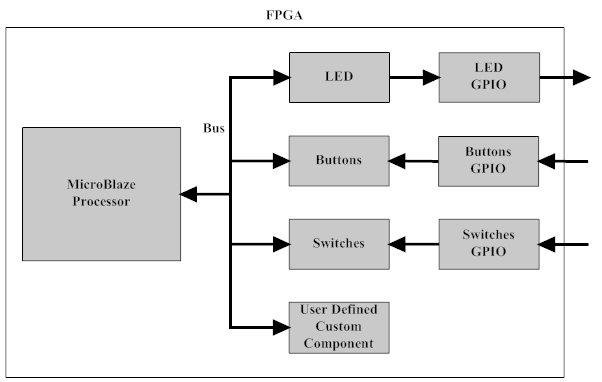 Figure: Shows the connections between the MicroBlaze and peripherals. ObjectiveToday, you will be programming synchronous state machines in C on the MicroBlaze processor and communicating with peripherals. You will follow the tutorial to create a MicroBlaze IP core with peripherals and add your own custom peripherals. Then you edit the C file in the Xilinx EDK tool in order to complete the lab. Your objectives help you gain familiarity with the IO devices on your FPGA development board such as LEDs, switches, buttons, etc. You are required to complete your objectives using the synchronous state machine design paradigm. Before beginning any parts complete the three Tutorials belowTutorial EDK: Using Base System BuilderTutorial SDK: Write a software application with SDKTutorial EDK: Create a Peripheral using the Peripheral WizardPart 1 - UART Hello WorldUse the peripherals on the MicroBlaze PLB bus to communicate with the PC via UART. Using the UART protocol, you can send/receive text with the MicroBlaze. The peripheral can be added using the Base System Builder when starting a new project, or by adding it from the IP Catalog in EDK. The easiest method is to use the Base System Builder. The RS232 peripheral can be controlled by using function calls to the device driver. An example usage of the function is: xil_printf("CS122A is Legend... wait for it DARY!\n"); Part 2 - LED BounceWrite a synchronous state machine that bounces the 8 LEDs on the board up and down. To start light 1 should turn on, followed by only light 2, then only light 3, and so on until the end is reached and the direction reverses back towards the first light. The lights should move at a pace the eye can see! Remember there are no interrupts shown yet, so you will need no operation loops to slow the led switching down. Part 3 - Custom peripheral (cycle counter)Using what you learned so far, create a custom cycle counter peripheral. The cycle counter should start counting with a start command, freeze counting with a stop command, print current count with a print command, and finally reset with a reset command. Extra Credit - Echo FSMWrite a synchronous state machine that echoes the values of the switches on the LEDs and to the UART, but only when Button 0 is pressed and released. In this implementation use interrupts! Here is a link to other tutorials to use interrupts. |