Write a software application with SDK
In the previous tutorial
Creating a project using
Base System Builder, we used the Embedded Development Kit (EDK)
to create a hardware design composed of IP cores and a MicroBlaze soft
processor. In this tutorial, we will complete the design by writing
a software application to run on the MicroBlaze processor. In version
13.2, this is done using the Software Development Kit (SDK) and it is
no longer "double" in the EDK. To keep things simple, we will start
off with a "hello world" application and then move onto one that will
communicate with our peripherals. Specifically, we will read the DIP
switch settings and display them on the terminal screen using printfs.
Requirements
To perform this tutorial, you will need:
- Xilinx ISE Design Suite 13.2
- Spartan-3E Starter Board
- Serial Cable
Export the EDK project to SDK
- If it is not already the case, you will need to copy the EDK
project files into the "C:\Spartan3EStarterBoard\Projects"
folder and build the bitstream as done in the tutorial. Note, it
does not have to be in C-drive and it does not have to be in the
Spartan3EStarterBoard/Projects folder, but above this,
try to use the same folder structure as we do here.
- Open EDK by selecting "Start->All Programs->Xilinx ISE Design
Suite 13.2->EDK->Xilinx Platform Studio".
- Open the Spartan3EStarterBoard base system project.
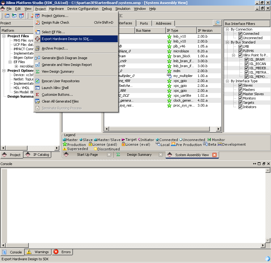
- From the EDK menu, select "Project->Export hardware design to
SDK".
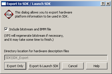
- In the dialog box that appears, make sure that "Include Bitstream
and BMM file" is ticked and click "Export Only".
- If you did not build the EDK project earlier, it will begin
to build the bitstream which may take some time (maybe half an hour
depending on your machine). After that, the project will have been
exported to SDK and you can continue.
Start SDK
- Open SDK by selecting "Start->All Programs->Xilinx ISE Design
Suite 13.2->EDK->Xilinx Software Development Kit".
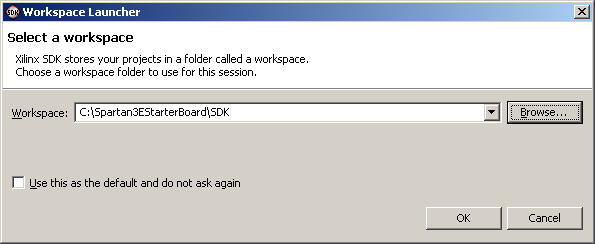
- The first thing you will be asked by SDK is what workspace to
open.
What are SDK Workspaces?
Think of the SDK workspace as a folder where you will manage
the software application(s) for one particular EDK hardware
design. You can place the workspace anywhere on your machine,
but I personally like to organize my projects in a folder structure
as follows:
- Spartan3EStarterBoard: The high-level folder that uses
the name of my project.
- edk: The sub-folder with my EDK project files.
- sdk: The sub-folder with my SDK project files.
In the example above, my project name is "Spartan3EStarterBoard"
which tells me its the base system project that I made using
version 13.2 of the Xilinx suite.
- Select "C:\Spartan3EStarterBoard\SDK" for your SDK
workspace and click OK.
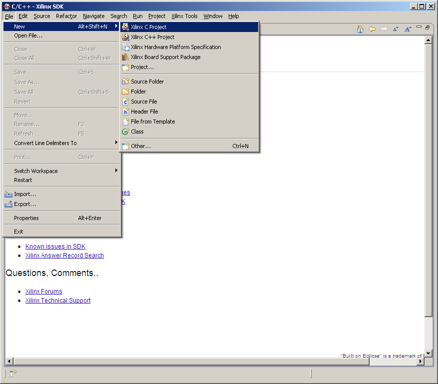
- SDK opens up with a welcome screen. Select "File->New->Xilinx
C project".
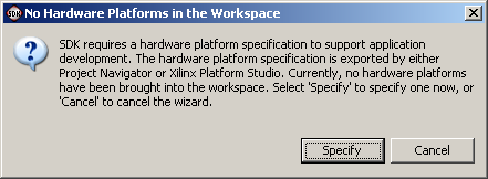
- You will then be asked to specify a hardware platform. Click
"Specify".
- In the dialog box that appears, type the name of the project
as "base-system-v13-1″ and use the browse button to navigate to
the "Spartan3EStarterBoard/SDK/SDK_Export/hw/system.xml"
file. This file was created by EDK when we exported the project
to SDK. If you cannot find this file, close SDK, open EDK and re-perform
the "Export to SDK" step.
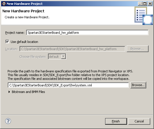
- Click Finish.
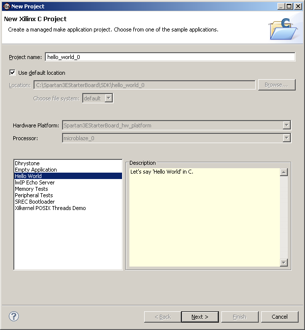
- The wizard that follows will allow us to create a template software
application for our project. The default is the "hello world" example
and we want to start with this one. Click Next to accept the defaults
as shown in the image below.
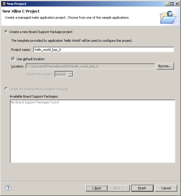
- Click Finish to accept the defaults of the second page.
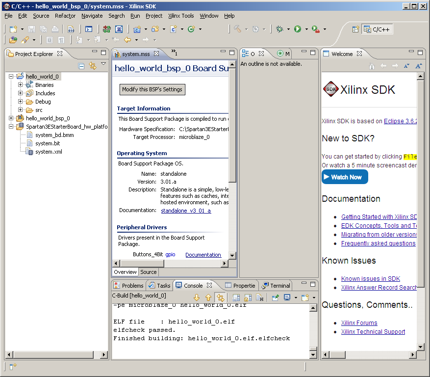
- If you did everything correctly, you should have the SDK window
looking like the image below.
Load the FPGA with the bitstream
- Open Cutecom the same as in Lab 3 Part 1 by typing "cutecom&"
in a terminal. The set up options for the serial connection are:
Device (/dev/ttyS0) Baud Rate (9600), Data bits (8), Stop bits (1)
Parity (none), Open for (Reading/Writing).
- Turn on your Spartan-3E Starter Board.
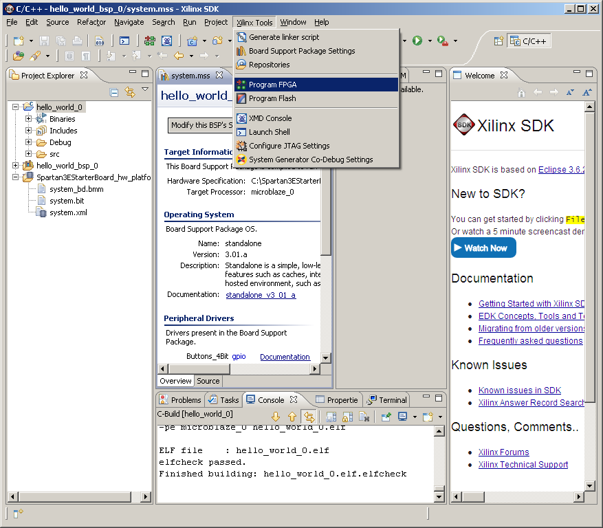
- From the SDK menu, select "Xilinx Tools->Program FPGA".
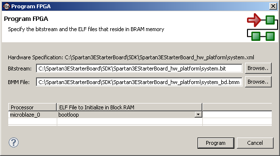
- In the "Program FPGA" dialog box, the defaults should already
specify the correct bitstream for the hardware project. Make sure
they correspond to the image above and click Program.
Run the Software Application
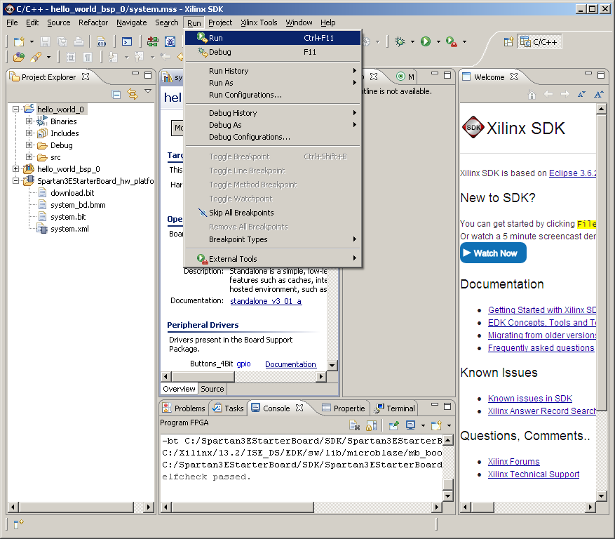
- From the SDK menu, select "Run->Run".
- In the "Run As" dialog box, select "Launch on Hardware".
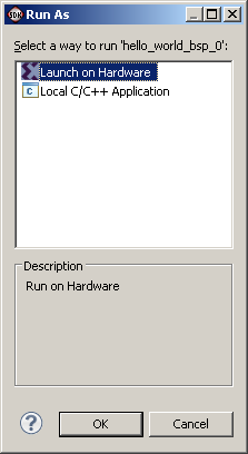
- SDK will build the software application, load it into the memory
on the FPGA and trigger the MicroBlaze to run the code. You should
see the words "Hello World" written in your terminal window.
|