Introduction to Xilinx Tools
Basics of VHDL
Table of Contents
Xilinx Documentation
Using the Lab Machines
Using Xilinx ISE 13
Synthesis,
Placement, Routing, and Simulation
Load a bitstream
to the Spartan 3E
ISE
ISE 13 In-Depth Tutorial
EDK
EDK 13.2 Tutorial
EDK - MicroBlaze Processor Reference Guide
Synthesis
Synthesis and Simulation Design Guide
UCF
Constraints Guide
Spartan-3E
User Guide
Advanced User Guide
Development Boards
Spartan 3E Starter Board
Spartan 3E-1600 Development Board
Spartan-6 FPGA Board
Welcome to the world of embedded systems. Today you will get an
introduction to the Xilinx ISE software. You will be implementing
a simple embedded system to get you familiar to the tools.
To open Xilinx ISE on a lab machine, first login and open a terminal.
Type vmware to start a windows virtual machine. Xilinx ISE
is on the desktop of the virtual machine windows operating system.
Also remember all content saved on the virtual machine will be erased
on shutdown, so before shutting down; save your files to your CSE
folder by mapping the drive or using WinSCP.
YOU MUST shutdown VMWare by going to start > shutdown in the start
menu. Simply pressing the X in the top right corner of the
window will not exit the process, and lock other users from starting
a virtual machine on the desktop.
This tutorial will help you become familiar with using Xilinx ISE
13 to develop on a Xilinx based FPGA board.
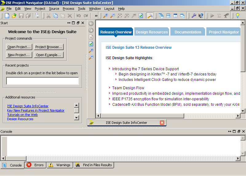
Step 1: Project Setup
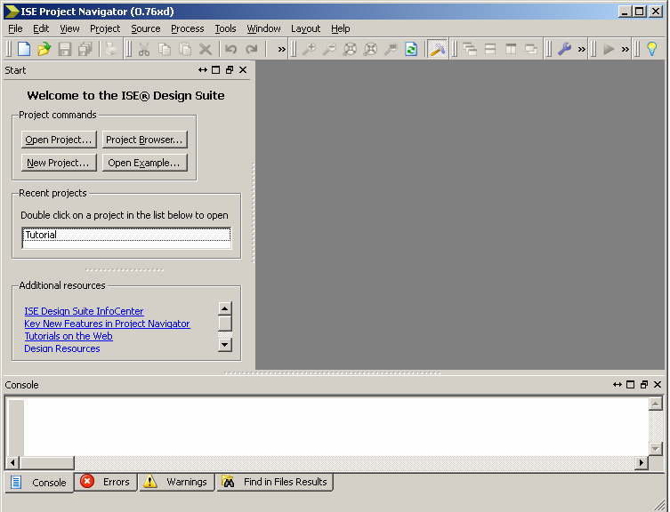
- Open Xilinx ISE Design Suite 13
- Select a New Project...
Note: If you are not prompted to create a new project, start
the new project wizard by selecting New Project in the
File menu.
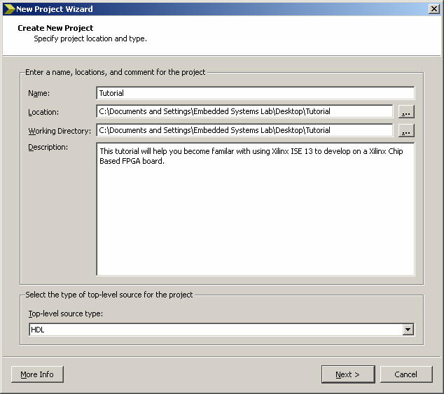
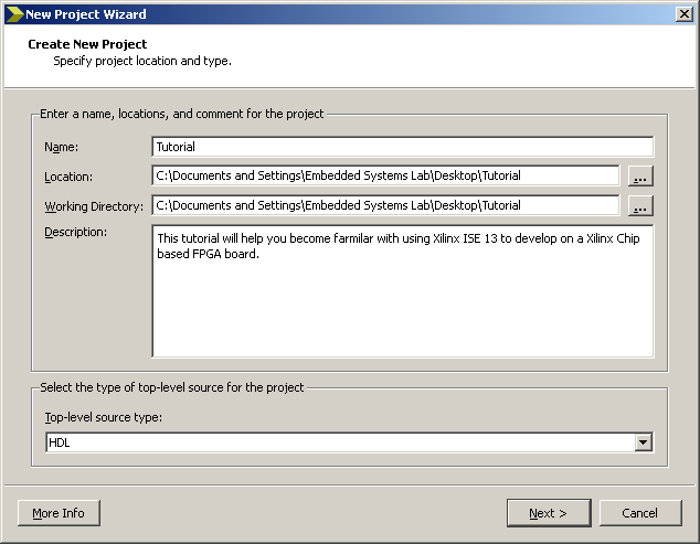
- Enter the desired project folder name.
(I.E. Tutorial)
Enter the desired project folder location.
(I.E. C:\Documents and Settings\Embedded Systems Lab\Desktop\)
Enter a Description of the Project.
Select Next >
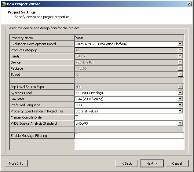
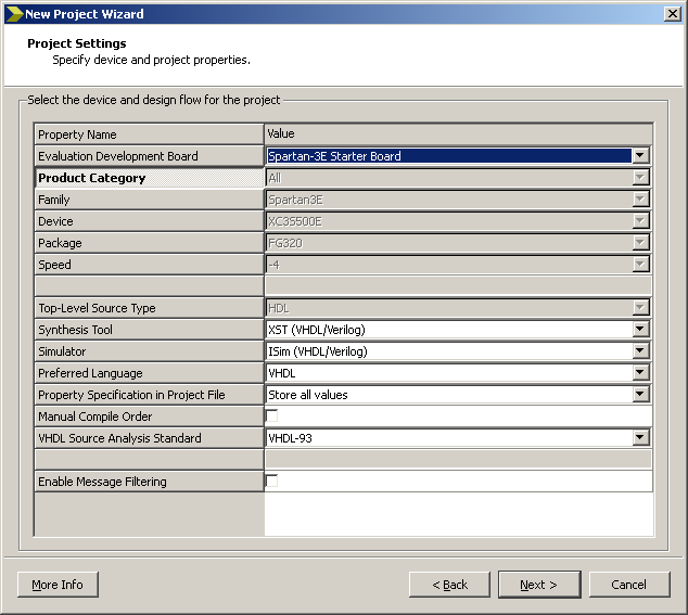
- Select the Evaluation Development Board, if known.
(I.E. Spartan-3E Starter Board)
Otherwise, you will have to look at the FPGA physical board
chip or product documentation for the Family, Device, Package,
and Speed.
Other settings are shown below.
Synthesis Tool: XST (VHDL/Verilog)
Simulator: ISim (VHDL/Verilog)
Preferred Language: VHDL Property Specification in Project
File: Store all Values
Manual Compile Order: Unselected
VHDL Source Analysis Standard: VHDL-93
Enable Message Filtering: Unselected
Select Next >
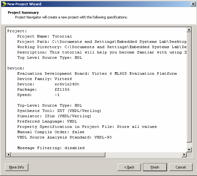
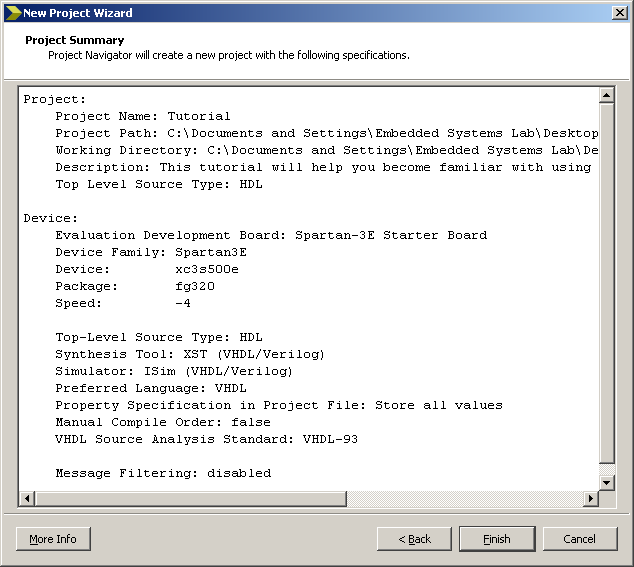
- A Project Summary will then be shown. Review the content
for correctness and select Finish if correct, otherwise
repeat the previous steps.
Step 2: Entity Setup
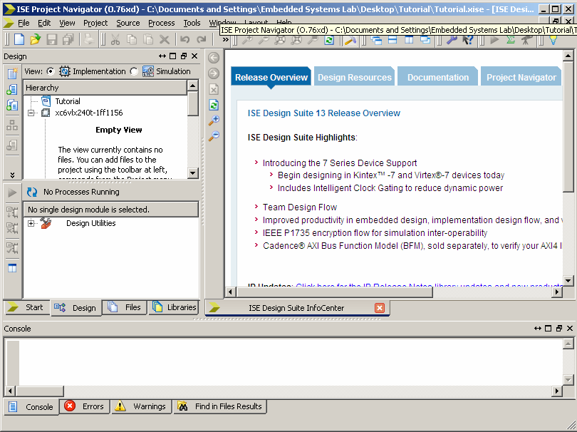
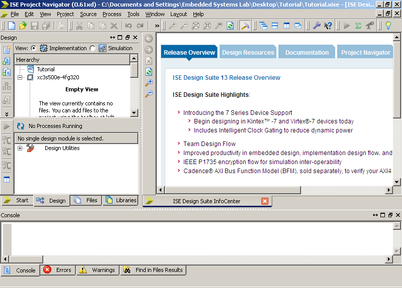
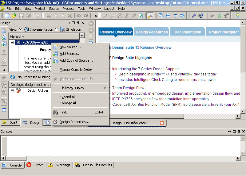
- You are now viewing the Project Navigator. The Sources in
the Project section will automatically organize your VHDL module
tree (Top Left). The Processes for Source pane will allow you
to perform various processes such as synthesis or device programming,
view reports, and access useful tools (Middle Left). The bottom
pane contains console output - notice the Console, Errors, Warnings
tabs; these are useful in debugging (bottom section). The right
are is used to display any files or documents you have opened.
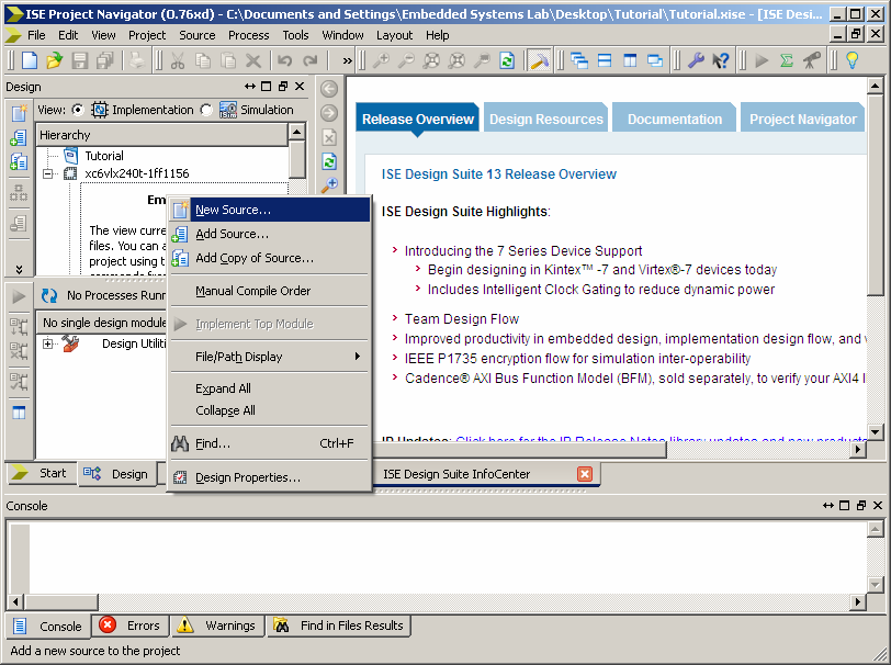
- Now you will create a new VHDL entity.
Right-Click on the chip icon and select New Source.
Take note that you can add already created sources.
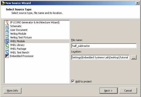
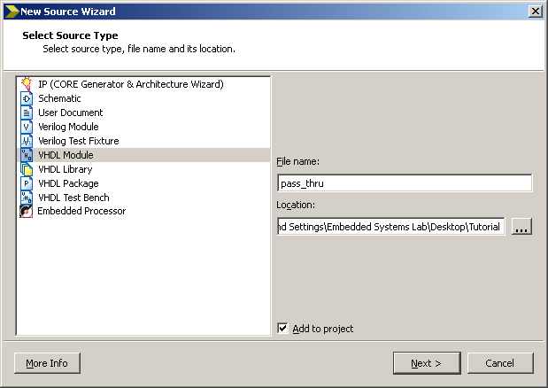
- Select VHDL Module
Give the module a name.
(I.E. Pass_thru)
Select Next >
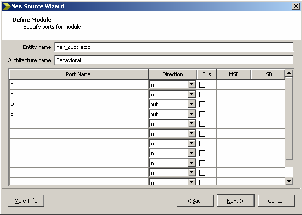
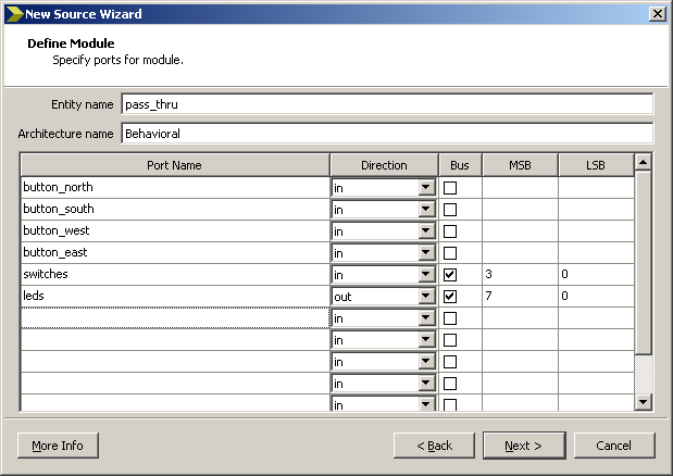
- The Entity name will near in its text box. The Architecture
name can also be changed in its text box as well, for this example
we are describing a Behavioral.
In the first Port Name text box give the port a name button_north,
since this is a single input it has no bus; do this for buttton_south,
buton_west, and button_west. We will be using these for input
signals so select "in" for the signal directions.
In the fifth Port Name text box give it the name switches, since
switches is group of multiple signals give these a bus by checking
the bus box and select the "in" data direction. We have four
switches on this particular board so select put "3" in MSB text
box, this is because we count the signal 3, 2, 1, and 0.
In the sixth Port Name text box give it the name leds, since
switches is group of multiple signals give these a bus by checking
the bus box and select the "out" data direction. We have eight
LEDs on this particular board so select put "7" in MSB text
box, this is because we count the signal 7, 6, 5, 4, 3, 2, 1,
and 0.
Select Next >
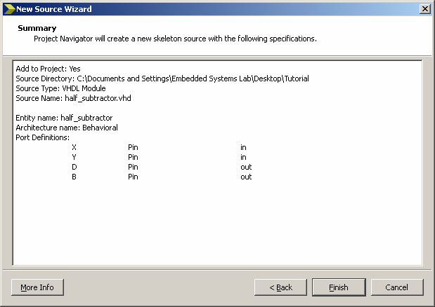
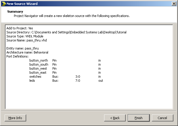
- Review the summary of the entity then Select Finish.
Step 3: Synthesis
- Enter the following
code.
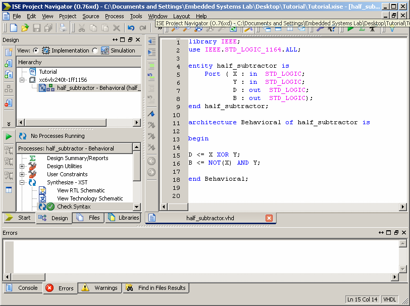
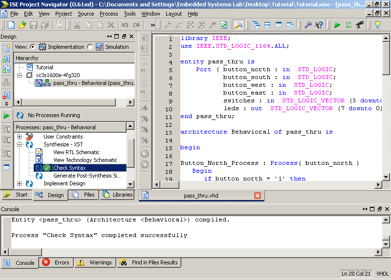
Once Entered, now we need to check if the VHDL syntax is correct.
Expand the Synthesize - XST tree and double click
Check Syntax.
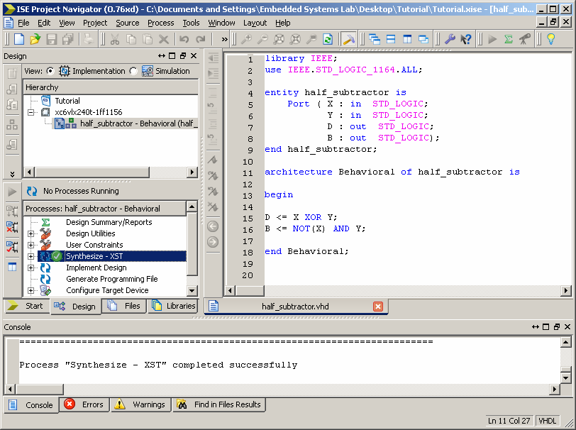
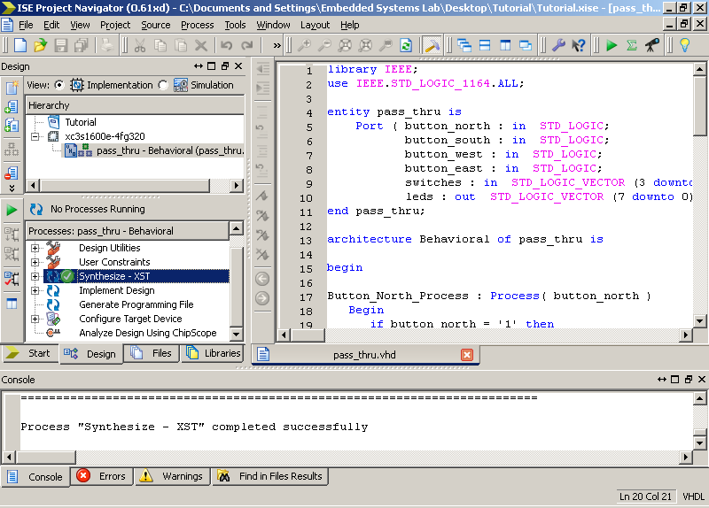
- If correct, then close tree and select Synthesize - XST
to check to make sure the code is synthesizable; there should
not be warnings or errors.
Step 4: Testbench
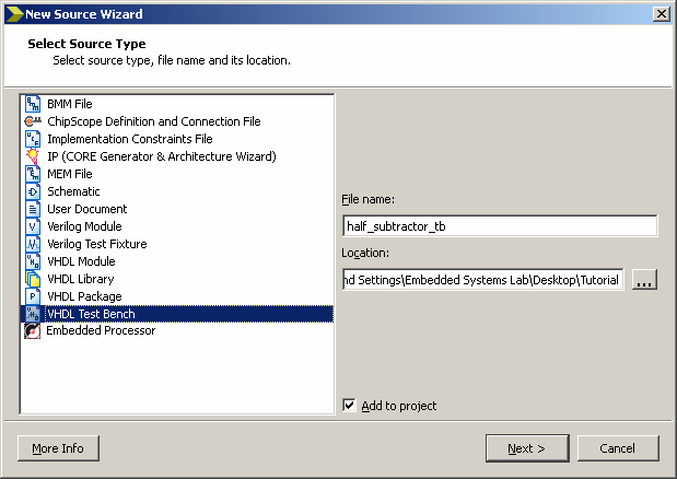
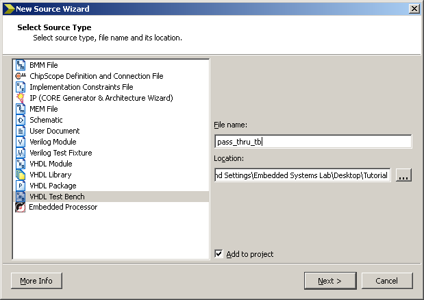
- Add a new source.
- Select VHDL Test Bench
File name: pass_thru_tb
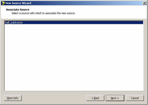
- Select Next >
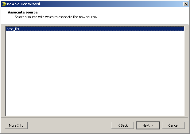
- Select pass_thru for the associate source.
- Select Next >
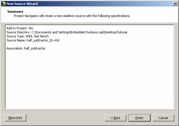
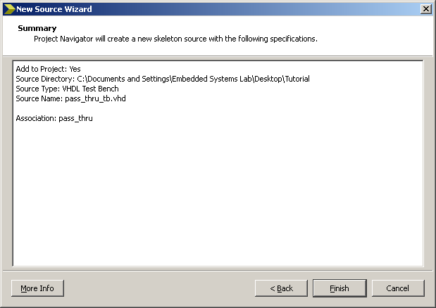
- Review the Summary and select Finish.
- Select the Simulation on the view button above the VHDL
module tree to see the testbench and simulation tree.
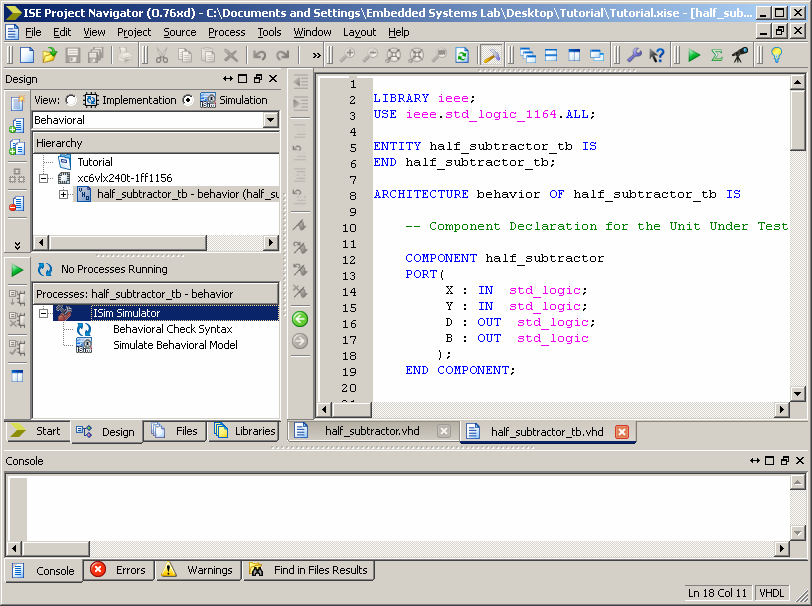
Enter the code.
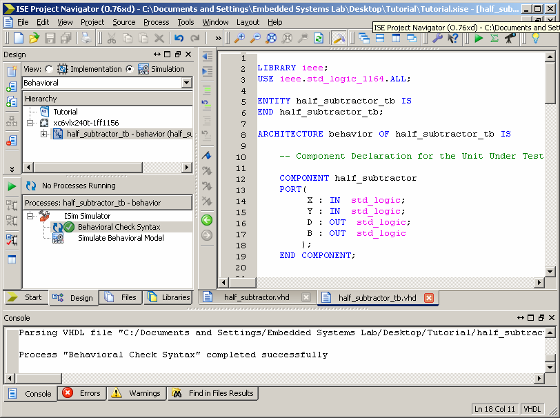
- In the Processes for Source pane expand the ISim Simulator
and double click the Behavioral Check Syntax. If correct then
there will be no errors.
- In the Processes for Source pane double click the Simulate
Behavior Model. A new window will appear showing the simulation.
If the test bench completes with no errors in the command prompt
then simulation was successful for the tested cases. You might
have to zoom out to view the signals in ns. Zoom out by pressing
F7 and zoom in by pressing F8 or use the shortcuts on the top
bar. Note: the testbench does not necessarily run to
the final wait statement. You might need to run the test until
you get the message "Note: Done with testbench".
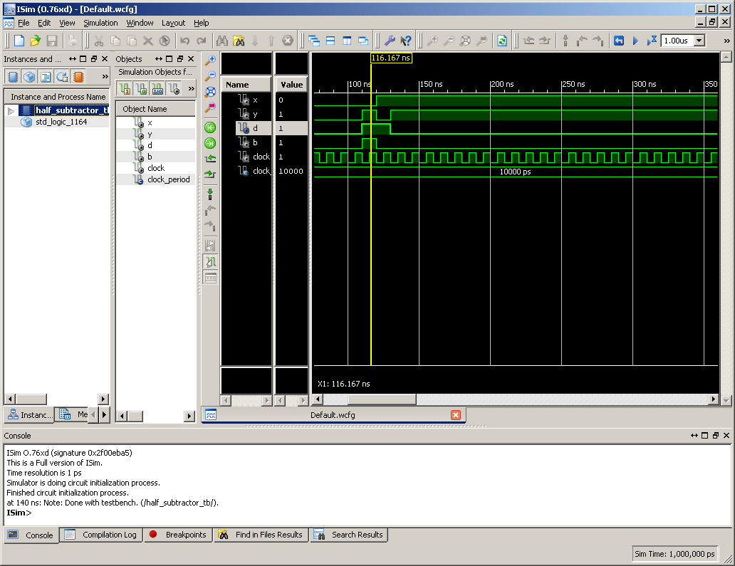
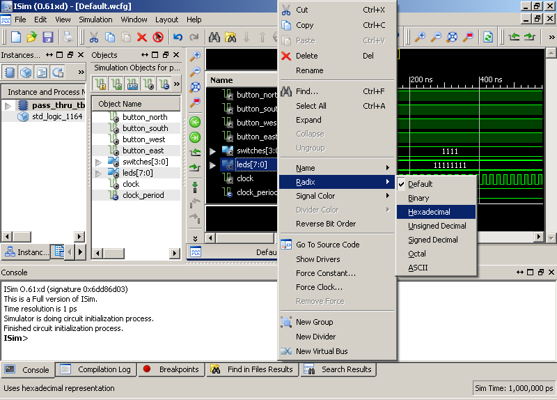
- You can also select the signals and change the display format
from binary to hexadecimal by selecting radix hexadecimal. Other
functionality includes: being able to add signals to the test
bench from internal signals, by dragging signals/variables from
the center pane to the right most pane. Other components can
be explored by expanding and selecting object in the left most
pane.
- Switch back to implementation view to continue editing.
Step 5: Additional Modules
- Repeat the processes above to add the full subtractor. Then
select it as the top module to do syntax and synthesis. Switching
modules is essential in testing components when adding modules.
Enter the following code.
- Repeat the processes for the full subtractor testbench. Enter
the following code.
Step 6: Inheriting Modules
- Repeat the processes above to add the generic subtractor. Then
select it as the top module to do syntax and synthesis. Switching
modules is essential in testing components when adding modules.
Enter the following
code.
- Repeat the processes for the generic subtractor testbench. Enter
the following code.
- When the design has been fully tested in synthesis and simulation,
then you proceed to the implementation to see the area and speed
of your design.
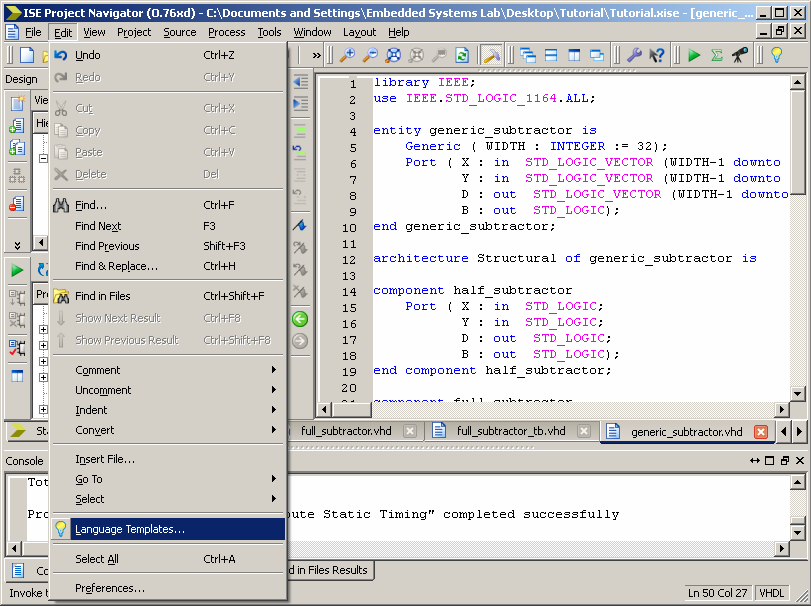
Step 7: VHDL templates
- Templates are a very useful resource for engineers. Unlike many
other programming languages, only a subset of VHDL can be synthesized
to hardware implementation. To access the language templates: go
to Edit > Language Templates.
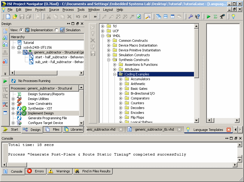
- In viewing the template look only at VHDL > Synthesis Constructs
> Coding Examples when design hardware. These templates will give
you an intuition for how to create hardware structures.
This tutorial will help you become familiar with using Xilinx ISE
13 to develop on a Xilinx based FPGA board.
Step 1: Project Setup
- Open Xilinx ISE Design Suite 13.2
- Select a New Project...
Note: If you are not prompted to create a new project, start
the new project wizard by selecting New Project in the
File menu.
- Enter the desired project folder name.
(I.E. Tutorial)
Enter the desired project folder location.
(I.E. C:\Documents and Settings\Embedded Systems Lab\Desktop\)
Enter a Description of the Project.
Select Next >
- Select the Evaluation Development Board, if known.
(I.E. Spartan-3E Starter Board)
Otherwise, you will have to look at the FPGA physical board
chip or product documentation for the Family, Device, Package,
and Speed.
Other settings are shown below.
Synthesis Tool: XST (VHDL/Verilog)
Simulator: ISim (VHDL/Verilog)
Preferred Language: VHDL Property Specification in Project
File: Store all Values
Manual Compile Order: Unselected
VHDL Source Analysis Standard: VHDL-93
Enable Message Filtering: Unselected
Select Next >
- A Project Summary will then be shown. Review the content
for correctness and select Finish if correct, otherwise
repeat the previous steps.
Step 2: Entity Setup
- You are now viewing the Project Navigator. The Sources in
the Project section will automatically organize your VHDL module
tree (Top Left). The Processes for Source pane will allow you
to perform various processes such as synthesis or device programming,
view reports, and access useful tools (Middle Left). The bottom
pane contains console output - notice the Console, Errors, Warnings
tabs; these are useful in debugging (Bottom). The right are
is used to display any files or documents you have opened.
- Now you will create a new VHDL entity.
Right-Click on the chip icon and select New Source.
Take note that you can add already created sources.
- Select VHDL Module
Give the module a name.
(I.E. Pass_thru)
Select Next >
- The Entity name will near in its text box. The Architecture
name can also be changed in its text box as well, for this example
we are describing a Behavioral.
In the first Port Name text box give the port a name button_north,
since this is a single input it has no bus; do this for buttton_south,
buton_west, and button_west. We will be using these for input
signals so select "in" for the signal directions.
In the fifth Port Name text box give it the name switches, since
switches is group of multiple signals give these a bus by checking
the bus box and select the "in" data direction. We have four
switches on this particular board so select put "3" in MSB text
box, this is because we count the signal 3, 2, 1, and 0.
In the sixth Port Name text box give it the name leds, since
switches is group of multiple signals give these a bus by checking
the bus box and select the "out" data direction. We have eight
LEDs on this particular board so select put "7" in MSB text
box, this is because we count the signal 7, 6, 5, 4, 3, 2, 1,
and 0.
Select Next >
- Review the summary of the entity then Select Finish.
Step 3: Synthesis
- Enter the following
code below.
|
library
IEEE;
use
IEEE.STD_LOGIC_1164.ALL;
entity
pass_thru
is
Port
(
button_north
:
in
STD_LOGIC;
button_south
:
in
STD_LOGIC;
button_west
:
in
STD_LOGIC;
button_east
:
in
STD_LOGIC;
switches
:
in
STD_LOGIC_VECTOR
(3
downto
0);
leds
:
out
STD_LOGIC_VECTOR
(7
downto
0));
end
pass_thru;
architecture
Behavioral
of
pass_thru
is
begin
Button_North_Process
:
Process(
button_north
)
Begin
if
button_north
=
'1'
then
leds(0)
<=
'1';
else
leds(0)
<=
'0';
end
if;
end
process
Button_North_Process;
Button_South_Process
:
Process(
button_south
)
Begin
if
button_south
=
'1'
then
leds(1)
<=
'1';
else
leds(1)
<=
'0';
end
if;
end
process
Button_South_Process;
Button_West_Process
:
Process(
button_west
)
Begin
if
button_west
=
'1'
then
leds(2)
<=
'1';
else
leds(2)
<=
'0';
end
if;
end
process
Button_West_Process;
Button_East_Process
:
Process(
button_east
)
Begin
if
button_east
=
'1'
then
leds(3)
<=
'1';
else
leds(3)
<=
'0';
end
if;
end
process
Button_East_Process;
with
switches
select
leds(7
downto
4)
<=
X"1"
when
X"1",
X"2"
when
X"2",
X"3"
when
X"3",
X"4"
when
X"4",
X"5"
when
X"5",
X"6"
when
X"6",
X"7"
when
X"7",
X"8"
when
X"8",
X"9"
when
X"9",
X"A"
when
X"A",
X"B"
when
X"B",
X"C"
when
X"C",
X"D"
when
X"D",
X"E"
when
X"E",
X"F"
when
X"F",
X"0"
when
others;
end
Behavioral;
|
Once Entered, now we need to check if the VHDL syntax is correct.
Expand the Synthesize - XST tree and double click
Check Syntax.
- If correct, then close tree and select Synthesize - XST
to check to make sure the code is synthesizable; there should
not be warnings or errors.
Step 4: Testbench
- Add a new source.
- Select VHDL Test Bench
File name: pass_thru_tb
- Select Next >
- Select pass_thru for the associate source.
- Select Next >
- Review the Summary and select Finish.
- Select the Simulation on the view button above the VHDL
module tree to see the testbench and simulation tree.
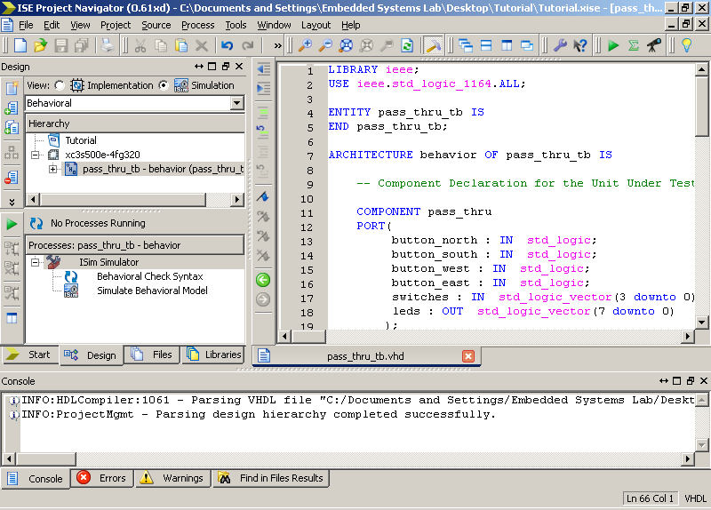
Enter the code below.
|
LIBRARY
ieee;
USE
ieee.std_logic_1164.ALL;
ENTITY
pass_thru_tb
IS
END
pass_thru_tb;
ARCHITECTURE
behavior
OF
pass_thru_tb
IS
-- Component Declaration for the Unit Under Test (UUT)
COMPONENT
pass_thru
PORT(
button_north
:
IN
std_logic;
button_south
:
IN
std_logic;
button_west
:
IN
std_logic;
button_east
:
IN
std_logic;
switches
:
IN
std_logic_vector(3
downto
0);
leds
:
OUT
std_logic_vector(7
downto
0)
);
END
COMPONENT;
--Inputs
signal
button_north
:
std_logic
:=
'0';
signal
button_south
:
std_logic
:=
'0';
signal
button_west
:
std_logic
:=
'0';
signal
button_east
:
std_logic
:=
'0';
signal
switches
:
std_logic_vector(3
downto
0)
:=
(others
=>
'0');
--Outputs
signal
leds
:
std_logic_vector(7
downto
0);
--Clock
signal
clock
:
std_logic
:=
'0';
constant
clock_period
:
time
:=
20
ns;
BEGIN
-- Instantiate the Unit Under Test (UUT)
uut:
pass_thru
PORT
MAP
(
button_north
=>
button_north,
button_south
=>
button_south,
button_west
=>
button_west,
button_east
=>
button_east,
switches
=>
switches,
leds
=>
leds
);
-- Clock process definitions
clock_process
:process
begin
clock
<=
'0';
wait
for
clock_period/2;
clock
<=
'1';
wait
for
clock_period/2;
end
process;
-- Stimulus process
stim_proc:
process
begin
-- hold reset state for 10 ns.
button_north
<=
'0';
button_south
<=
'0';
button_west
<=
'0';
button_east
<=
'0';
switches
<=
X"0";
wait
for
10
ns;
wait
for
clock_period;
-- insert stimulus here
--Error Check OFF
button_north
<=
'0';
button_south
<=
'0';
button_west
<=
'0';
button_east
<=
'0';
switches
<=
X"0";
wait
for
clock_period;
Assert
(
leds
=
X"00"
)
Report
"Error : leds = x00"
Severity
ERROR;
--Error Check ON
button_north
<=
'1';
button_south
<=
'1';
button_west
<=
'1';
button_east
<=
'1';
switches
<=
X"F";
wait
for
clock_period;
Assert
(
leds
=
X"FF"
)
Report
"Error : leds = xFF"
Severity
ERROR;
wait;
end
process;
END;
|
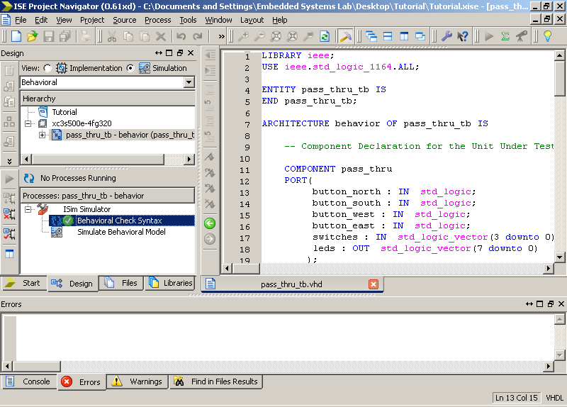
- In the Processes for Source pane expand the ISim Simulator
and double click the Behavioral Check Syntax. If correct then
there will be no errors.
- In the Processes for Source pane double click the Simulate
Behavior Model. A new window will appear showing the simulation.
If the test bench completes with no errors in the command prompt
then simulation was successful for the tested cases. You might
have to zoom out to view the signals in ns. Zoom out by pressing
F7 and zoom in by pressing F8 or use the shortcuts on the top
bar.
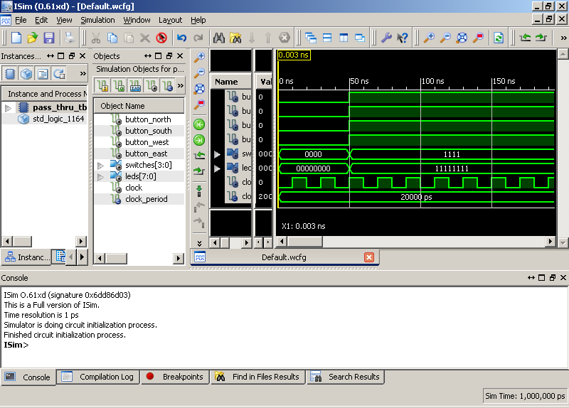
- You can also select the signals and change the display format
from binary to hexadecimal by selecting radix hexadecimal.
- Switch back to implementation view.
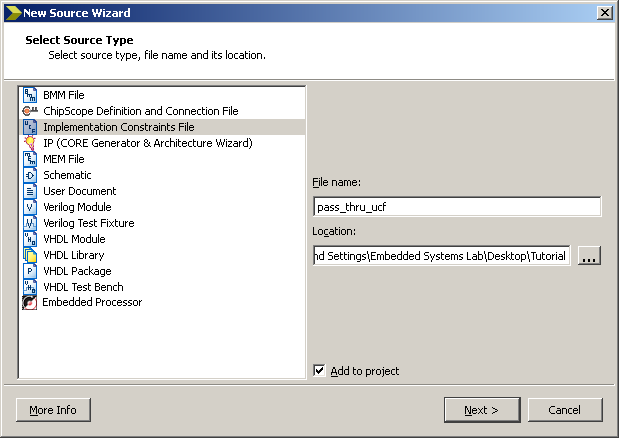
Step 5: UCF
- Add a new source.
- Select Implementation Constraints File
File name: pass_thru_ucf
- Select Next >
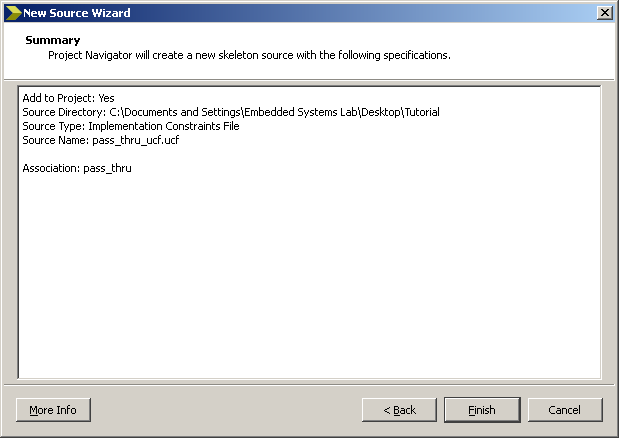
- Review the Summary and select Finish.
You can view the UCF file in the tree and open it by selecting
the file in the entity tree. Then in the Processes for Source
pane expand the User Constraints tree and double clicking
Edit Constraints.
Enter the code below
to map the inputs and outputs.
#BUTTONS
NET "button_north" LOC = "V4" | IOSTANDARD = LVTTL |
PULLDOWN;
NET "button_south" LOC = "K17" | IOSTANDARD = LVTTL
| PULLDOWN;
NET "button_west" LOC = "D18" | IOSTANDARD = LVTTL |
PULLDOWN;
NET "button_east" LOC = "H13" | IOSTANDARD = LVTTL |
PULLDOWN;
#SWITCHES
NET "switches<0>" LOC = "L13" | IOSTANDARD = LVTTL |
PULLUP;
NET "switches<1>" LOC = "L14" | IOSTANDARD = LVTTL |
PULLUP;
NET "switches<2>" LOC = "H18" | IOSTANDARD = LVTTL |
PULLUP;
NET "switches<3>" LOC = "N17" | IOSTANDARD = LVTTL |
PULLUP;
#LEDS
NET "leds<0>" LOC = "F12" | IOSTANDARD = LVTTL | SLEW
= SLOW | DRIVE = 8;
NET "leds<1>" LOC = "E12" | IOSTANDARD = LVTTL | SLEW
= SLOW | DRIVE = 8;
NET "leds<2>" LOC = "E11" | IOSTANDARD = LVTTL | SLEW
= SLOW | DRIVE = 8;
NET "leds<3>" LOC = "F11" | IOSTANDARD = LVTTL | SLEW
= SLOW | DRIVE = 8;
NET "leds<4>" LOC = "C11" | IOSTANDARD = LVTTL | SLEW
= SLOW | DRIVE = 8;
NET "leds<5>" LOC = "D11" | IOSTANDARD = LVTTL | SLEW
= SLOW | DRIVE = 8;
NET "leds<6>" LOC = "E9" | IOSTANDARD = LVTTL | SLEW
= SLOW | DRIVE = 8;
NET "leds<7>" LOC = "F9" | IOSTANDARD = LVTTL | SLEW
= SLOW | DRIVE = 8; |
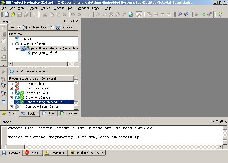
Step 6: Implement and Generate Programming File
- In the Processes for Source pane double click Generate Programming
File. The process will go through translation, technology mapping,
placement and routing, and lastly bit file generation.
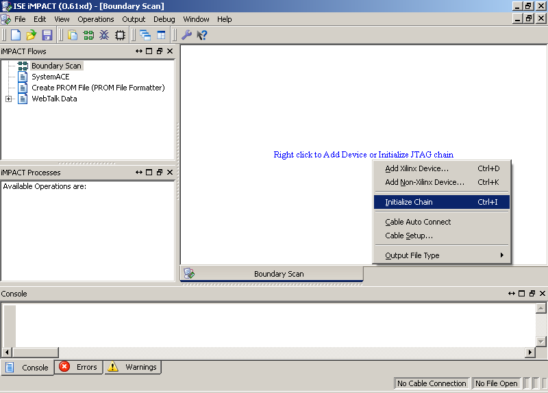
Step 7: Target Device
- Double click on Configure Target Device and the ISE iMPACT
window will open.
- Double click on Boundary Scan.
- Right click in the Boundary Scan area and select initialize
chain.
- Right click on the xc3s500e chip and assign the generated
.bit file from Step 6. Bypass the other chip programming.
- When successful you will get a Program Succeeded dialogue.
Refer to Xilinx Documentation for Advanced ISE Usage
|