Integrating a VHDL Design into a Peripheral
Tutorial Overview
In this tutorial we integrate one or more VHDL files. Sometimes we
have a VHDL design that we developed in ISE, or some other program,
and we would like to bring it into the EDK as a peripheral. In this
tutorial, we will create a multiplier peripheral.
The multiplier will take in two 16 bit unsigned inputs and have a
32 bit unsigned output. A single 32 bit write to the peripheral will
contain the two 16 bit inputs, separated by the lower and higher 16
bits. A single 32 bit read from the peripheral will contain the result
from the multiplication of the two 16 bit inputs. Instead of registers,
we will use a read and write FIFO for the interface with the software
application. In this way, the peripheral write FIFO can be loaded with
a number of multiplications to perform, and the results can be pushed
into the read FIFO for the software application to retrieve at its convenience.
Practically, this design does not serve much purpose, but it is a simple
demonstration of integrating VHDL designs into peripherals.
Create the Multiplier Peripheral
Follow these steps to create the multiplier peripheral.
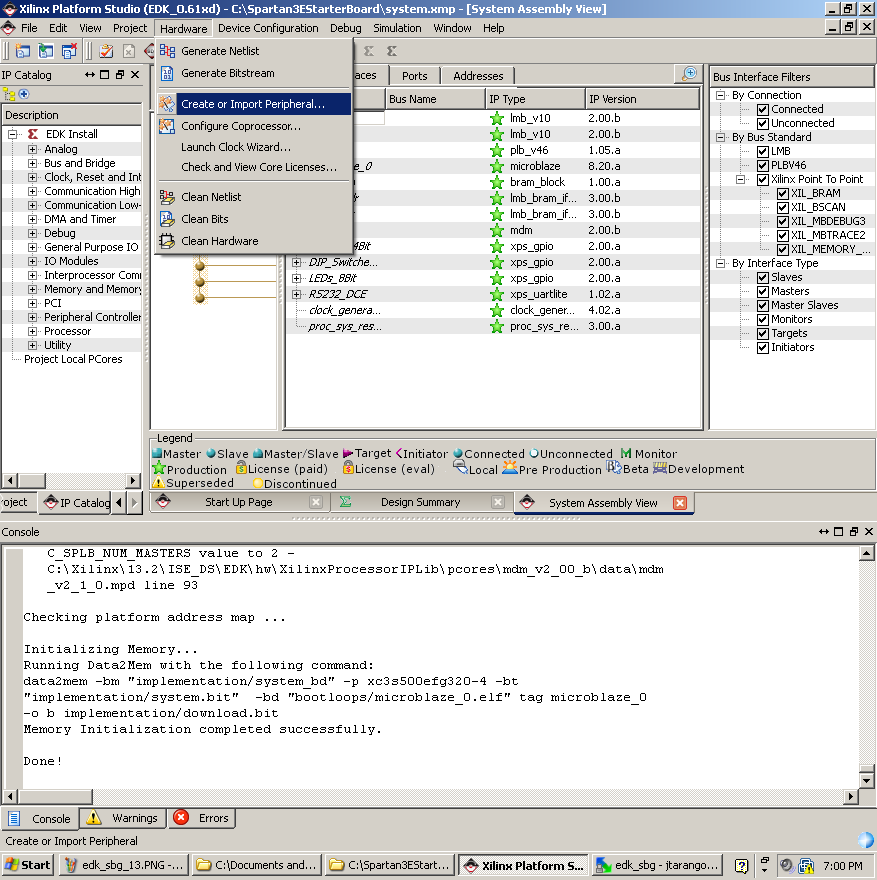
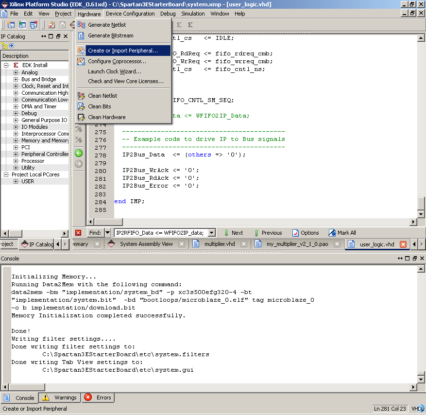
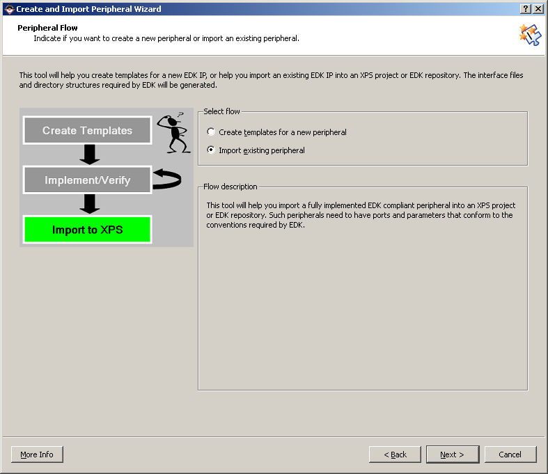
- Select from the menu "Hardware->Create or Import Peripheral".
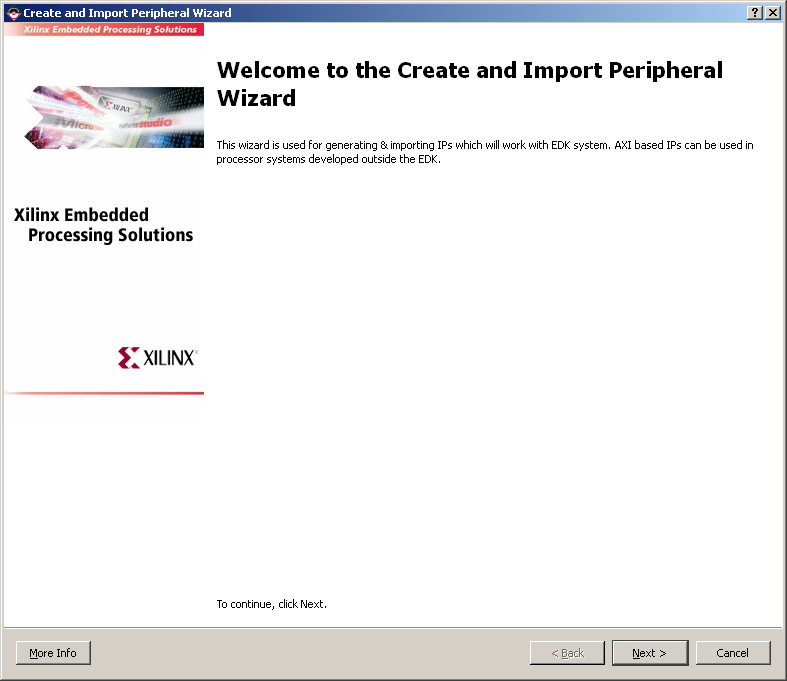
- Click "Next".
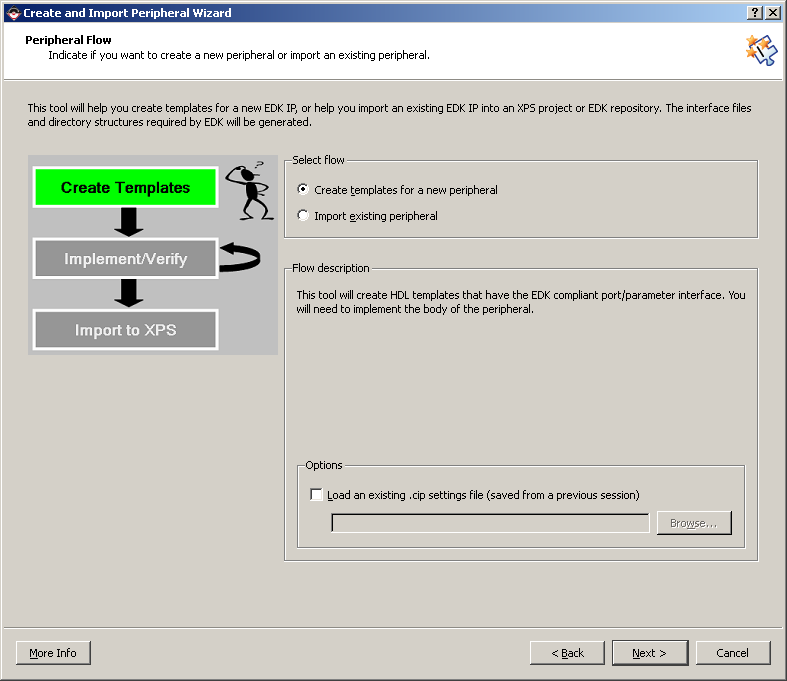
- Select "Create templates for a new peripheral" and click "Next".
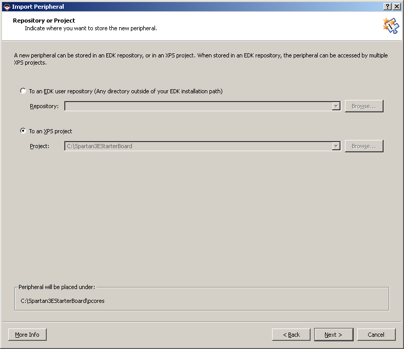
- We must now decide where to place the files for the peripheral.
They can be placed within this project, or they can be made accessible
to other projects. Select "To an XPS project". Click "Next".

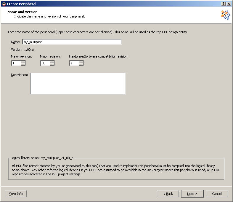
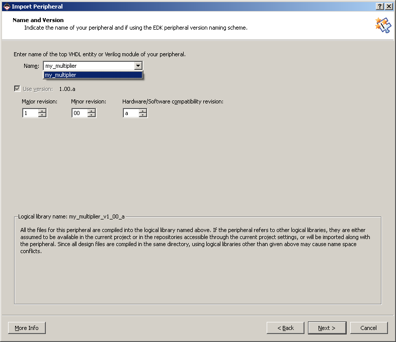
- On the "Name and Version" page, type "my_multiplier" for the
peripheral name. Click "Next".
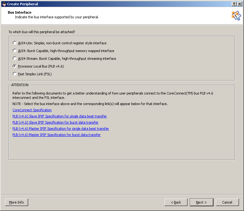
- On the "Bus Interface" page, select "Processor Local Bus" (PLB)
and click "Next".
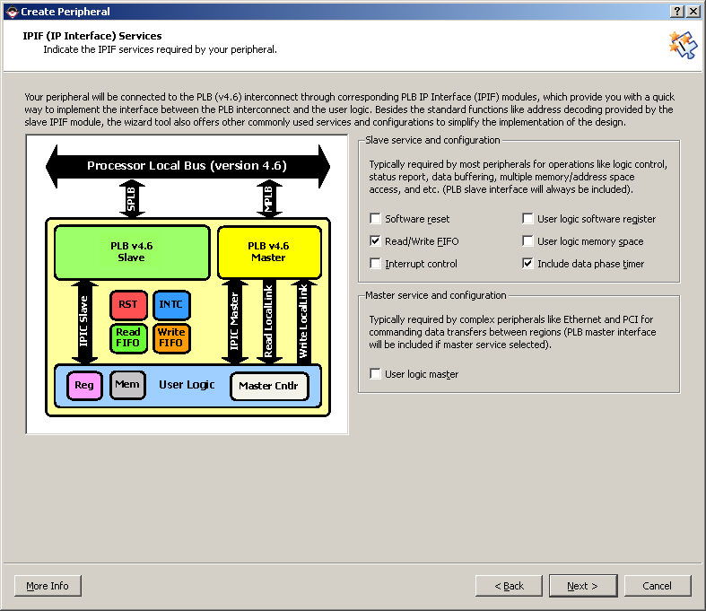
- On the "IPIF Services" page, we can make the Peripheral Wizard
generate our VHDL template to include different features. Select
"Read/Write FIFO" and "Include data phase timer", un-tick everything
else and click "Next".
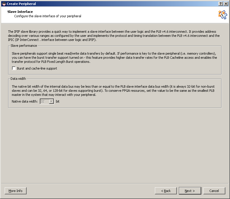
- On the "Slave Interface" page, click "Next".
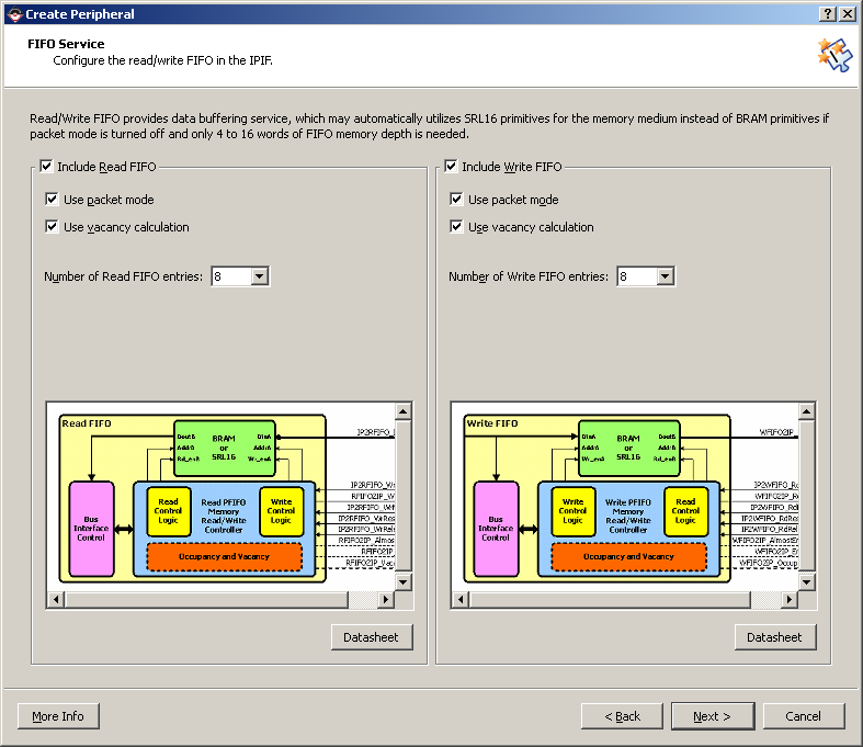
- For the FIFO Service settings, leave the defaults ticked: Include
read FIFO, Include write FIFO, Use packet mode, Use vacancy calculation.
Choose a FIFO depth of 8.
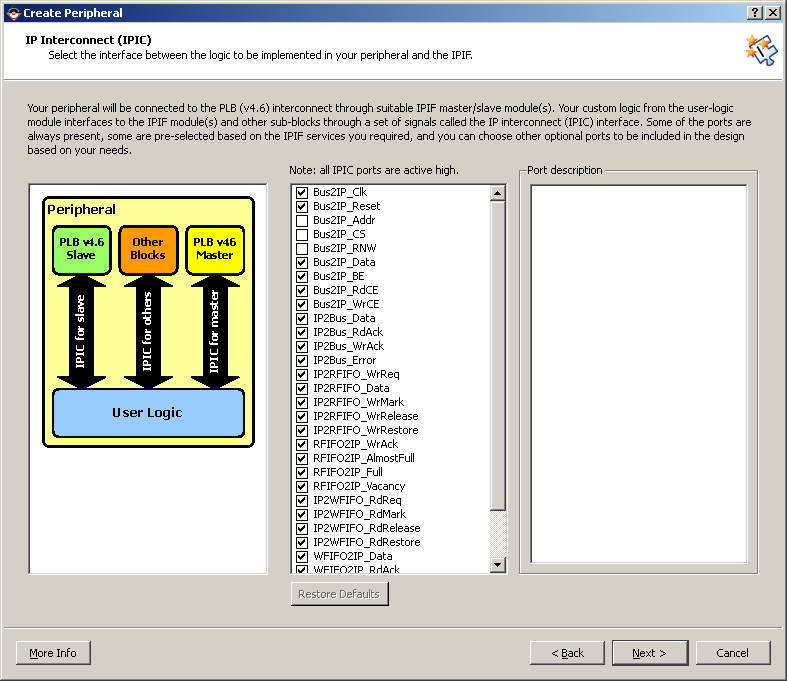
- On the "IP Interconnect" page we can customize our connection
to the PLB but we will leave everything as is for simplicity. Click
"Next".
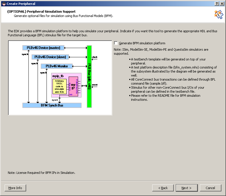
- On the "(OPTIONAL) Peripheral Simulation Support" page, we can
specify if we want the wizard to create a simulation platform for
our peripheral. Click "Next" without ticking the option to generate.
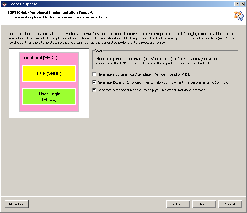
- After the "Peripheral Implementation Support" page, the wizard
will generate all the template files for us. Tick "Generate ISE
and XST project files" and "Generate template driver files". Click
"Next".
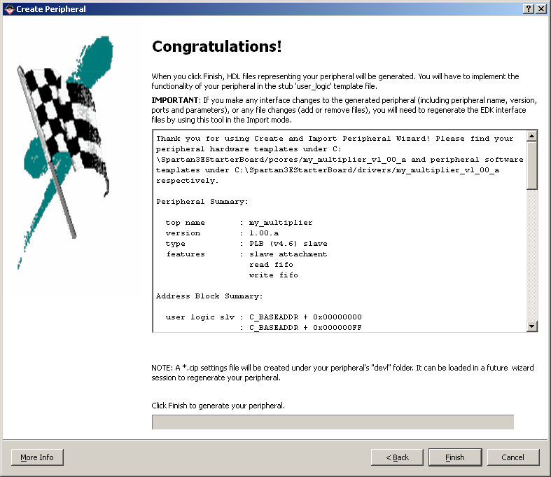
- Click "Finish". Now our templates are created.
Create the Multiplier core in VHDL
Follow these steps to create the Multiplier core:
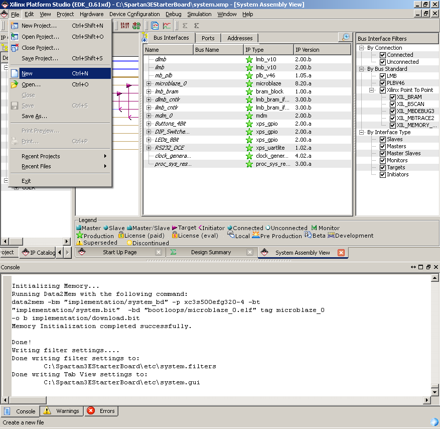
- Select "File->New". This will open a new text document that
we will use for the multiplier VHDL source code.
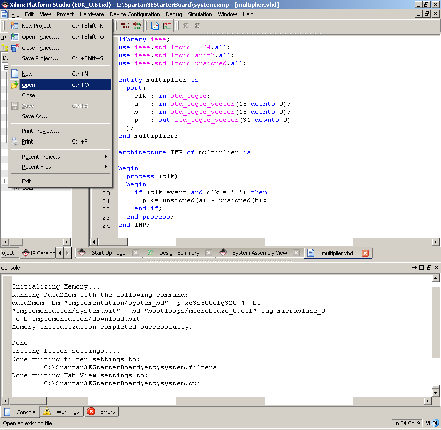
- Copy and paste the following code into the new text document.
Save the file as "multiplier.vhd" in the "pcores\my_multiplier_v1_00_a\hdl\vhdl"
folder.
library ieee;
use ieee.std_logic_1164.all;
use ieee.std_logic_arith.all;
use ieee.std_logic_unsigned.all;

entity multiplier is
  port(
    clk : in std_logic;
    a   : in std_logic_vector(15 downto 0);
    b   : in std_logic_vector(15 downto 0);
    p   : out std_logic_vector(31 downto 0)
  );
end multiplier;

architecture IMP of multiplier is

begin
  process (clk)
  begin
    if (clk'event and clk = '1') then
      p <= unsigned(a) * unsigned(b);
    end if;
  end process;
end IMP;
|
Modify the .PAO file
The .pao file contains a list of all the source files that compose
our peripheral. We use this list when we run the Peripheral Wizard
in Import mode. Now that we have added another source file to the
project ("multiplier.vhd"), we must include it in the .pao file.
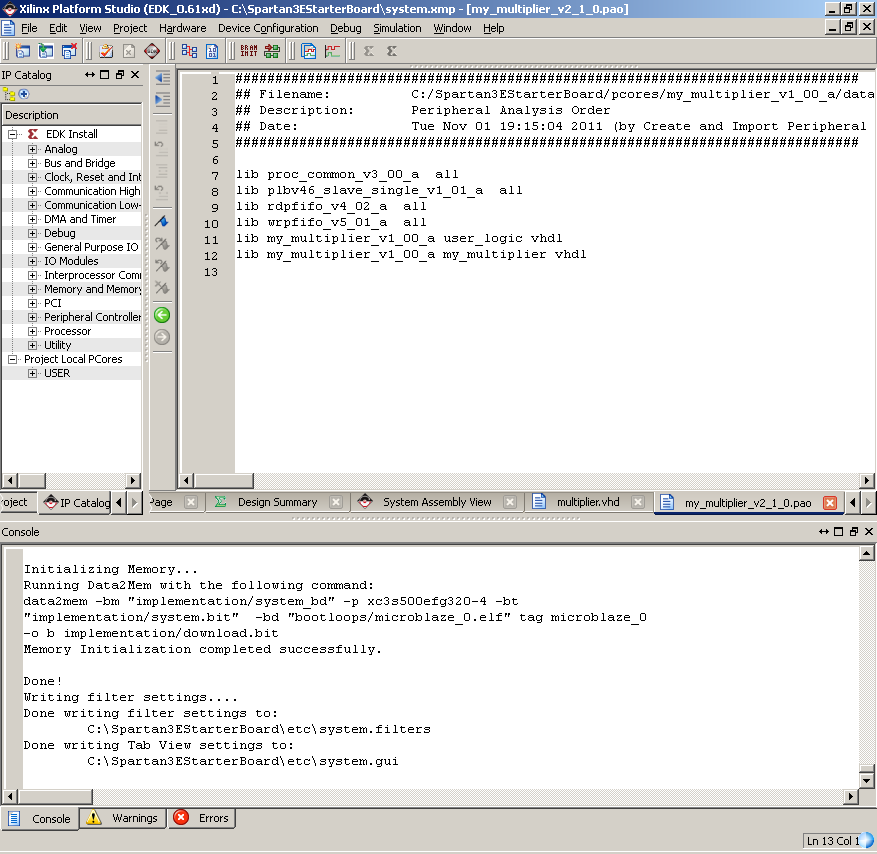
- Select "File->Open" and browse to the "pcores\my_multiplier_v1_00_a\data"
folder. Select the file "my_multiplier_v2_1_0.pao" and click "Open".
- At the bottom of this file you will see these two lines:
lib my_multiplier_v1_00_a user_logic vhdl
lib my_multiplier_v1_00_a my_multiplier vhdl
|
- Add the line "lib my_multiplier_v1_00_a multiplier vhdl" just
above those two lines.
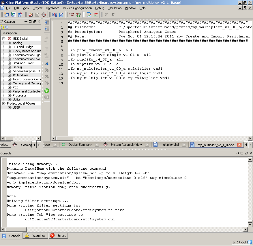
- Save the file.
Now we can use this .pao file with the Peripheral Wizard and
it will know to include the "multiplier.vhd" file in our design.
Notice that the .pao file lists the source files in hierarchical
order. Thus if you have a VHDL design consisting of multiple files,
it is important to know the hierarchical order of your components.
The components at the top of the chain are listed at the bottom
of the file.
Modify the Peripheral
Now we will add code in our peripheral template to instantiate
a multiplier core and we will connect it to the read and write FIFOs.
- Select from the menu "File->Open" and look in the project folder.
- Open the folders: "pcores\my_multiplier_v1_00_a\hdl\vhdl". This
folder contains two source files that describe our peripheral "my_multiplier.vhd"
and "user_logic.vhd". The first file is the main part of the peripheral
and it implements the interface to the OPB. The second file is where
we place our custom logic to make the peripheral do what we need
it to do. This part is instantiated by the first file.
- Open the file "user_logic.vhd". We will need to modify this
source code to instantiate the multiplier and connect it to the
read and write FIFOs.
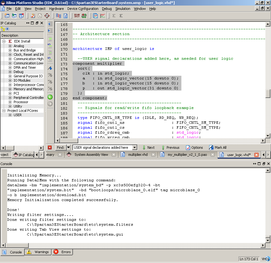
- Find the line of code that says "USER signal declarations added
here" and add the following lines of code just below.
component multiplier
   port(
      clk : in std_logic;
      a : in std_logic_vector(15 downto 0);
      b : in std_logic_vector(15 downto 0);
      p : out std_logic_vector(31 downto 0)
   );
end component;
|
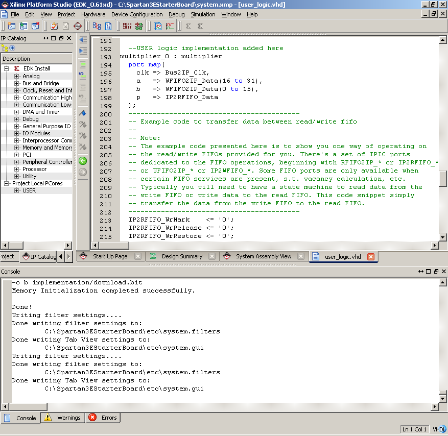
- Find the line of code that says "USER logic implementation added
here" and add the following lines of code just below.
multiplier_0 : multiplier
  port map (
    clk => Bus2IP_Clk,
    a => WFIFO2IP_Data(16 to 31),
    b => WFIFO2IP_Data(0 to 15),
    p => IP2RFIFO_Data
  );
|
- Find the line of code that says "IP2RFIFO_Data <= WFIFO2IP_Data;"
and comment it out (or delete it). Now, the read FIFO will be loaded
with data from the multiplier.
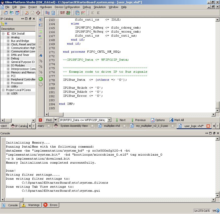
- Save and close the file.
Import the Multiplier Peripheral
Now we will use the Peripheral Wizard in Import mode.
- Select from the menu "Hardware->Create or Import Peripheral"
and click "Next".

- Select "Import existing peripheral" and click "Next".
- Select "To an XPS project", ensure that the folder chosen is
the project folder, and click "Next".
- For the name of the peripheral, select "my_multiplier". Tick
"Use version" and select the same version number that we originally
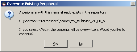
created. Click "Next". It will ask if we are willing to overwrite
the existing peripheral and we should answer "Yes".
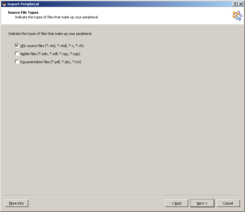
- Now we are asked about the files that make up our peripheral.
Tick "HDL source files" and click "Next".
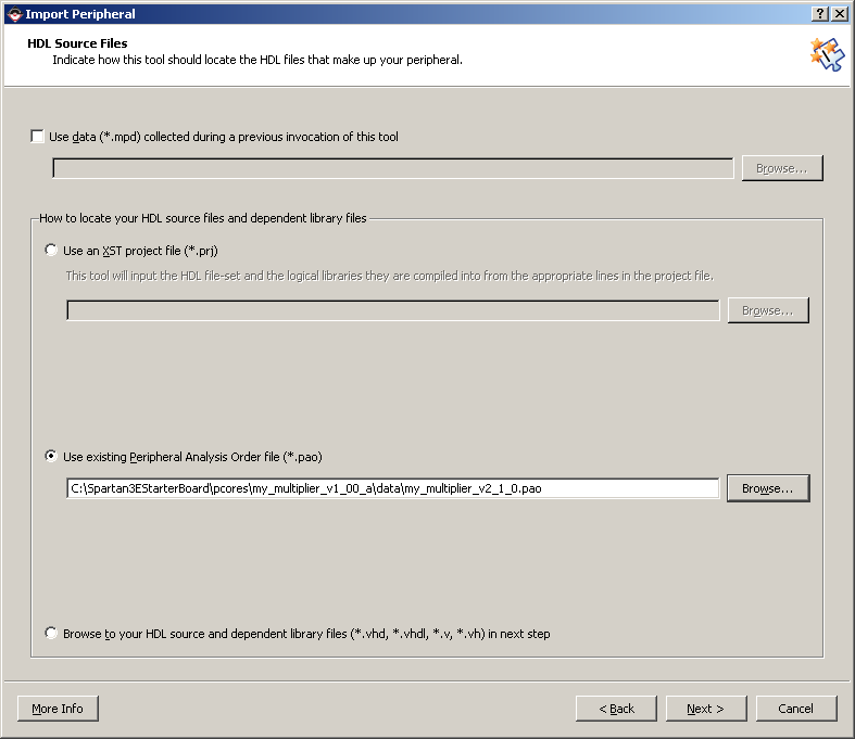
- Select "Use existing Peripheral Analysis Order file (*.pao)"
and click "Browse". From the project folder, go to "pcores\my_multiplier_v1_00_a\data"
and select the "my_multiplier_v2_1_0.pao" file. Click "Next".
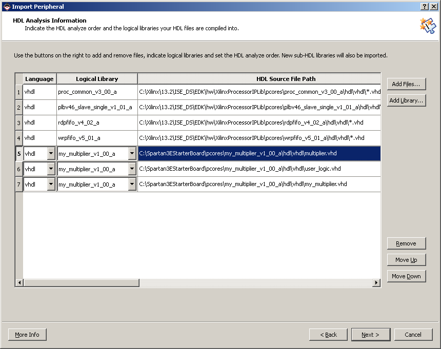
- On the HDL analysis information page, if you scroll down, you
will see the "multiplier.vhd" file listed third from the bottom.
Click "Next". The wizard will mention if any errors are found in
the design.
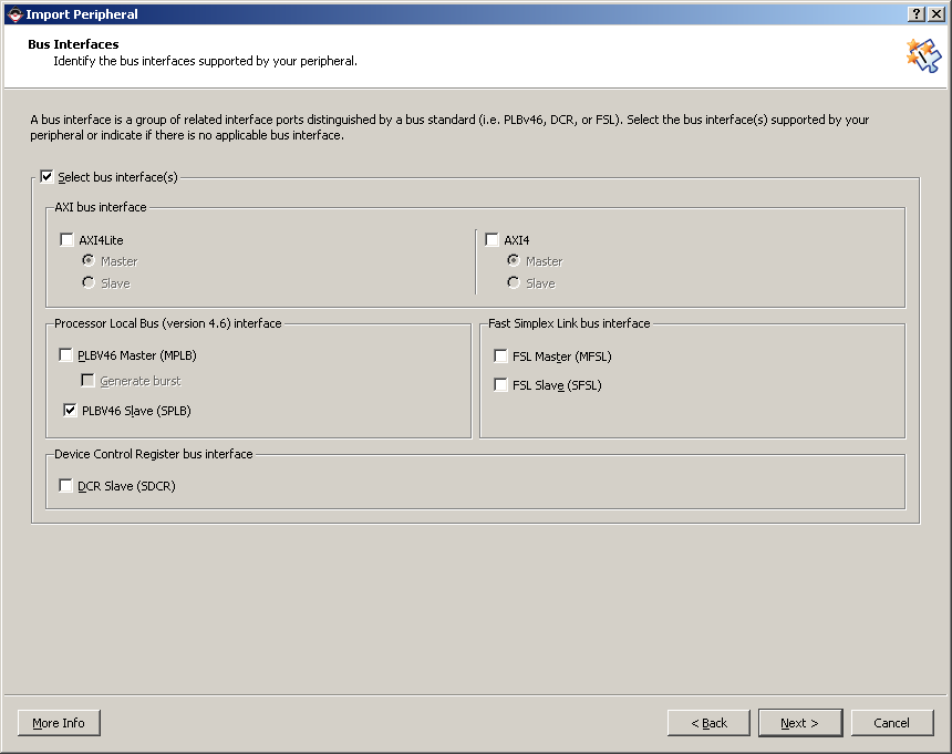
- On the Bus Interfaces page, tick "PLB Slave" and click "Next".
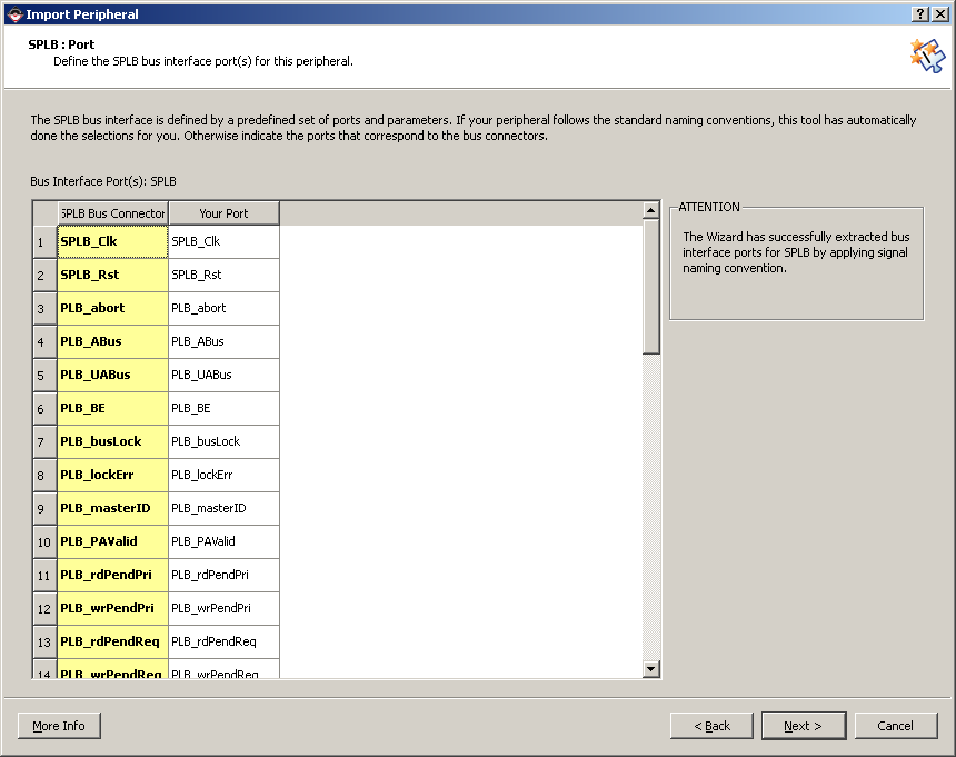
- On the SPLB: Port page, click "Next".
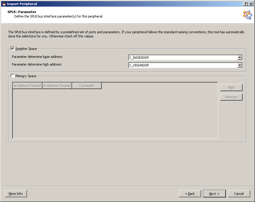
- On the SPLB: Parameter page, click "Next".
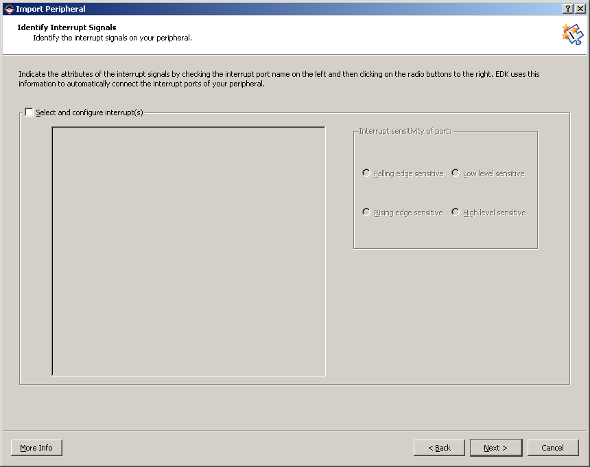
- On the Identify Interrupt Signals, un-tick "Select and configure
interrupt" then click "Next"
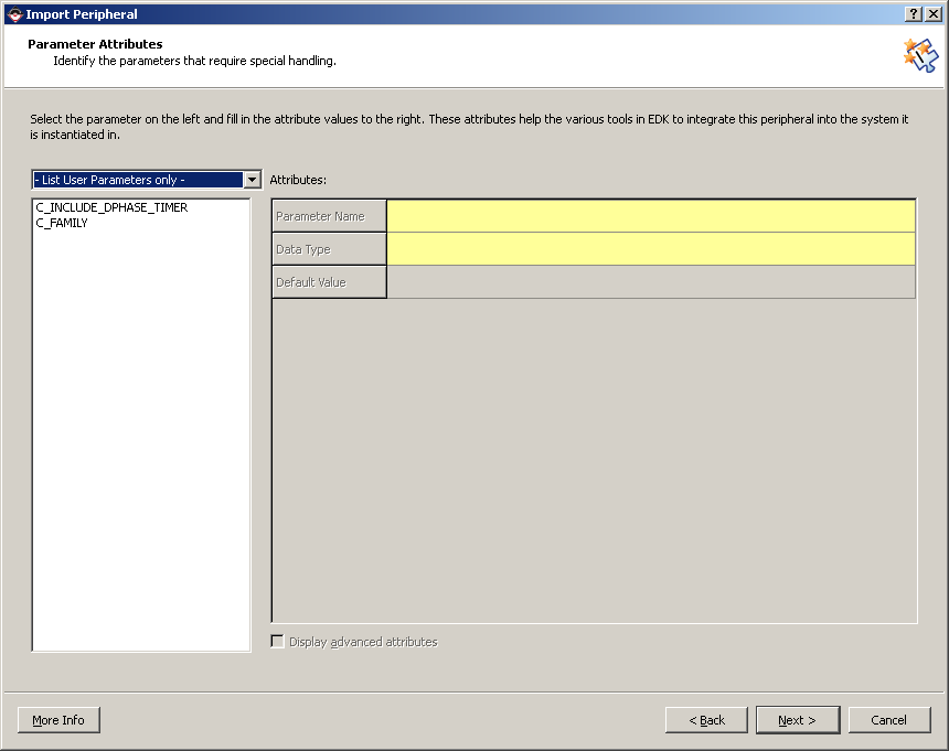
- On the "Parameter Attributes" page, make sure "List User Parameters
Only" is selected then click "Next".
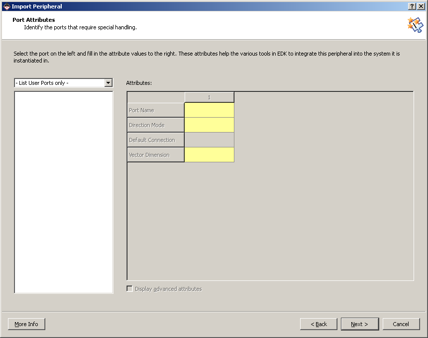
- On the "Port Attributes" page, make sure "List User Ports Only"
is selected then click "Next".
- Click "Finish".
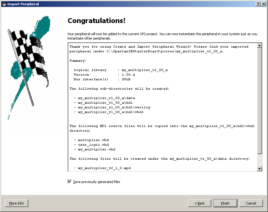
The multiplier peripheral should now be accessible through the
"IP Catalog->Project Local pcores" in the XPS interface.
Create an Instance of the Peripheral
Follow these steps to create an instance of the peripheral in
the project.
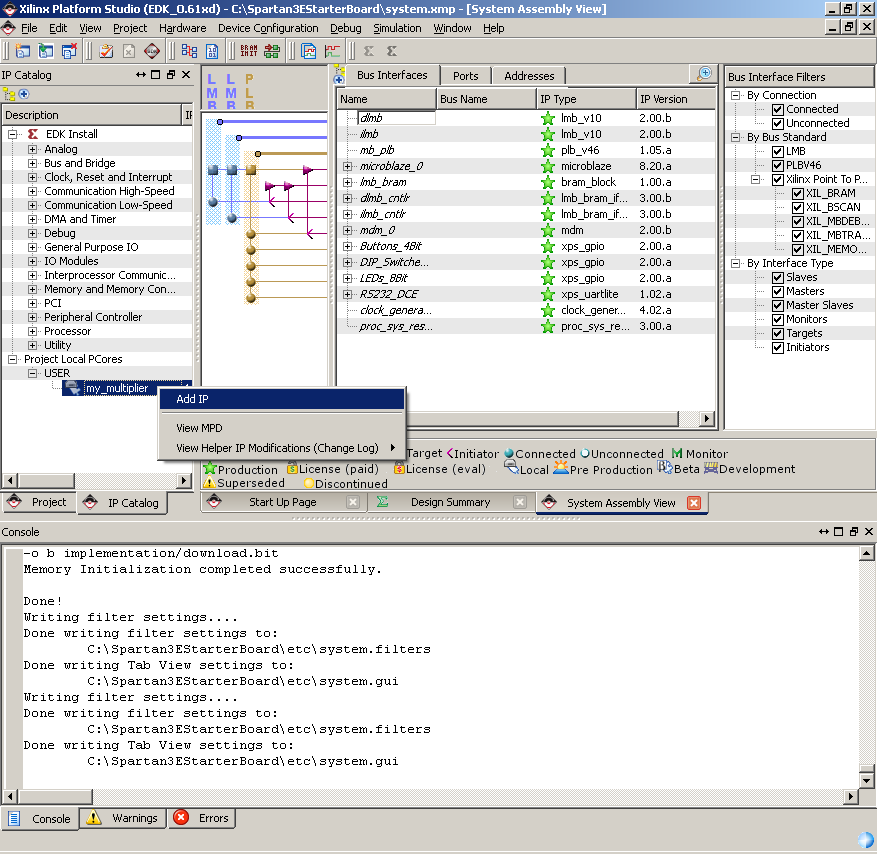
- From the "IP Catalog" find the "my_multiplier" IP core in the
"Project Repository" group. Right click on the core and select "Add
IP".
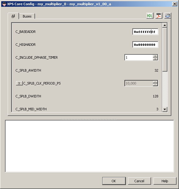
- A new window will open, click "OK". The dialogue is to select
the address range, since we are not selecting a valid range we will
get an error in the command line. Such as:
WARNING:EDK:2137 - Peripheral my_multiplier_0 is not accessible
from any processor in the system. Check Bus Interface connections
and address parameters.
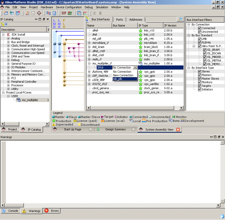
- From the "System Assembly View" using the "Bus Interface" filter,
connect the "my_multiplier_0″ to the PLB bus.
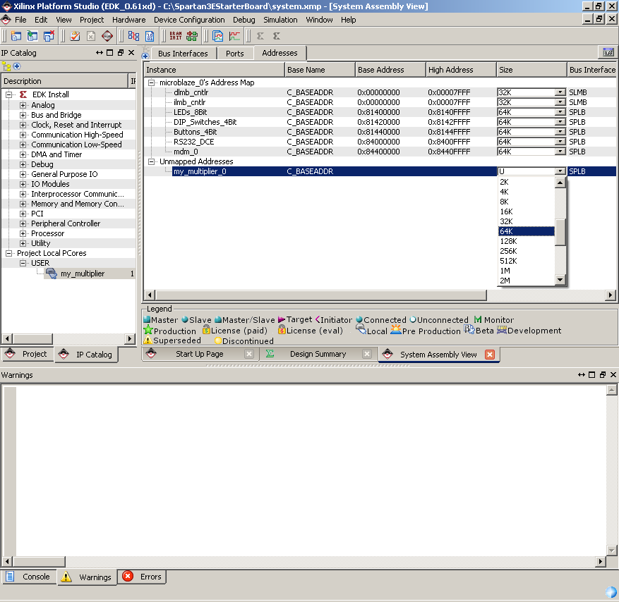
- Click on the "Addresses" filter. Change the "Size" for "my_multiplier_0"
to 64K. then click "Generate Addresses".
- Click "Generate Addresses" in the upper right hand corner of
the window.
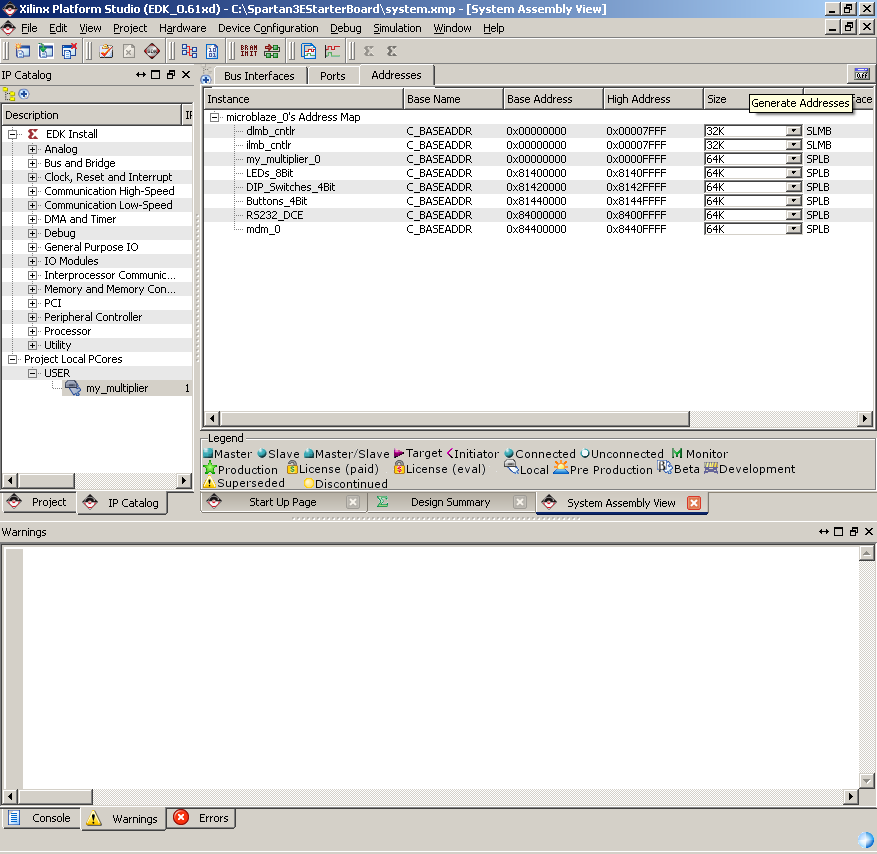
The Console will give you something like this output:
Address Map for Processor microblaze_0
  (0000000000-0x00007fff) dlmb_cntlr	dlmb
  (0000000000-0x00007fff) ilmb_cntlr	ilmb
  (0x81400000-0x8140ffff) LEDs_8Bit	mb_plb
  (0x81420000-0x8142ffff) DIP_Switches_4Bit	mb_plb
  (0x81440000-0x8144ffff) Buttons_4Bit	mb_plb
  (0x84000000-0x8400ffff) RS232_DCE	mb_plb
  (0x84400000-0x8440ffff) mdm_0	mb_plb
  (0xcde00000-0xcde0ffff) my_multiplier_0	mb_plb
Generated Addresses Successfully
Now we have an instance of the multiplier peripheral in our project
and our hardware design is complete.
Modify the Software Application
Now all we need to do is modify the software application to test
our multiplier peripheral.
- From SDK create a new "Xilinx C Project" and Select "Empty Application"
or "Peripheral Tests" (It is recommended to start from "Peripheral
Tests" because most of the other I/O pointers and libraries have
already been setup). Add the files from the "C:\Spartan3EStarterBoard\drivers\my_multiplier_v1_00_a\src"
to your new project "src" folder. If you are confused at this point
you need to complete the
SDK
tutorial.
- Use this code to test the design.
#include "xparameters.h"
#include "xbasic_types.h"
#include "xstatus.h"
#include "my_multiplier.h"

Xuint32 *baseaddr_p = (Xuint32 *)XPAR_MY_MULTIPLIER_0_BASEADDR;

int main (void) {
  Xuint32 i;
  Xuint32 temp;
  Xuint32 baseaddr;

  // Clear the screen
  xil_printf("%c[2J",27);

  // Check that the peripheral exists
  XASSERT_NONVOID(baseaddr_p != XNULL);
  baseaddr = (Xuint32) baseaddr_p;

  xil_printf("Multiplier Test\n\r");

  // Reset read and write packet FIFOs to initial state
  MY_MULTIPLIER_mResetWriteFIFO(baseaddr);
  MY_MULTIPLIER_mResetReadFIFO(baseaddr);

  // Push data to write packet FIFO
  for(i = 1; i <= 4; i++ ){
    temp = (i << 16) + i;
    xil_printf("Wrote: 0x%08x \n\r", temp);
    MY_MULTIPLIER_mWriteToFIFO(baseaddr,0, temp);
  }

  // pop data out from read packet FIFO
  for(i = 0; i < 4; i++){
    temp = MY_MULTIPLIER_mReadFromFIFO(baseaddr,0);
    xil_printf("Read:  0x%08x \n\r", temp);
  }

  // Reset the read and write FIFOs
  MY_MULTIPLIER_mResetWriteFIFO(baseaddr);
  MY_MULTIPLIER_mResetReadFIFO(baseaddr);

  xil_printf("End of test\n\n\r");

  // Stay in an infinite loop
  while(1){
  }
}
|
- Save and close the file.
Download and Test the Project
- Open Cutecom the same as in Lab 3 Part 1 by typing "cutecom&"
in a terminal. The set up options for the serial connection are:
Device (/dev/ttyS0) Baud Rate (9600), Data bits (8), Stop bits (1)
Parity (none), Open for (Reading/Writing).
- Turn on the Spartan-3E board.
- From the XPS software, select "Device Configuration->Download
Bitstream".
The output should look as shown below:
Multiplier Test
Wrote: 0x00010001
Wrote: 0x00020002
Wrote: 0x00030003
Wrote: 0x00040004
Read: 0x00000001
Read: 0x00000004
Read: 0x00000009
Read: 0x00000010
End of test
Remember, those numbers are in hexadecimal so 0x10 = 16!
|