|
Home |
|
Yes/No eBlock Catalog
| Sensor eBlocks |
| eBlock |
Diagram |
Description |
Interface |
| Button |
 |
Sensor detects when the button is pressed. |
yes = button pressed
no = button not pressed |
| Light Sensor |
 |
Sensor detects the presence of light. |
yes = light detected
no = light not detected |
| Magnetic Contact Switch |
 |
Sensor detects when a magnet is
near the sensor. |
yes = magnet near
no = magnet not near |
| Motion Sensor |
 |
Sensor detects the presence of motion. |
yes = motion detected
no = motion not detected |
| Light-Beam Switch |
 |
Sensor detects whem the light beam is broken. |
yes = beam broken
no = beam not broken |
| Sound Sensor |
 |
Sensor detects the presence of sound. |
yes = sound detected
no = sound not detected |
| Water Sensor |
 |
Sensor the presence of water. |
yes = water detected
no = water not detected |
| 3-Key Entry |
 |
Sensor detects if the sequence of keys are pressed
correctly. |
yes = proper sequence entered
no = proper sequence not entered |
| 10-Key Entry |
 |
Sensor detects if the sequence of keys are pressed
correctly. |
yes = proper sequence entered
no = proper sequence not entered |
| Output/Display eBlocks |
| eBlock |
Diagram |
Description |
Interface |
| Beeper |
 |
Device emits a beeping sound. |
yes = beeper on
no = beeper off |
| Green/Red light |
 |
Device emits a green or red light. |
yes = light is green
no = light is red |
| Normal light |
 |
Device emits a light. |
yes = light is on
no = light is off |
| Electric Relay |
 |
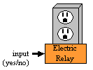
Device transmits electricity. |
yes = electricity on
no = electricity off |
| Electric Lock |
 |
Device locks and unlocks. |
yes = lock
no = unlock |
| Lightswitch |
 |
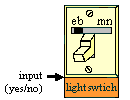
Light switch has 2 modes, eb and mn. In the
eBlock mode (eb) the lightswitch is controlled by other
eBlocks. If it recieves and input of yes then electricity is
tranmistted to devices controlled by the lightswitch. If it
recieves and input of no then no electricity is transmitted
to devices controlled by the lightswitch. In manual mode
(mn) the lightswitch is controlled by the switch on the
faceplate. |
In eb mode:
yes = electricity on
no = electricity off |
| Arithmetic/Logic eBlocks |
| eBlock |
Diagram |
Description |
Interface |
| 2-Input Logic |
 |
Device computes several logic functions
based on two
inputs. The corresponding logic function is programmed
by the user via a dipswitch. |

For each of the possible combinations of input a and b, there is
a corresponding switch which can be set so the resulting
output is a yes or no for that particular combination. |
| 3-Input Logic |
 |
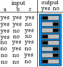
Device computes several logic
functions based on three
inputs. The corresponding logic function is programmed
by the user via a dipswitch. |

For each of the possible combinations of input a, b, and c
there is a corresponding switch which can be set so the resulting
output is a yes or no for that particular combination. |
| Inverter |
 |
Outputs the opposite of the input signal. |
yes = input is no
no = input is yes |
| Timer |
| eBlock |
Diagram |
Description |
Interface |
| Clock Timer |
 |
Device has a 24-hour clock. The user can set pins to
indicate at which times to toggle the output of the
device. |
yes = previous output was no and toggle
encountered
no = previous output was yes and toggle
encountered |
| Up/Down Timer |
 |
Count up mode:
User indicates time the timer counts up to. When the start input
is yes, the device will count up to the user indicated
time. When the rst input is yes the timer will start at zero
and count up to the user defined time again.
Count down mode:
User indicates the start time. When the start input
is yes the device counts down to zero. When the rst
input is yes the timers starts at the user defined time
and counts down to zero. |
INPUTS:
start = yes, start timer
start = no, stop timer
rst = yes, reset timer
rst = no, normal timer functionality
OUTPUT:
Count up mode:
yes = user defined time reached
no = user defined time not reached
Count down mode:
yes = time zero reached
no = time zero not reached |
| Alarm/Clock Timer |
 |
User first selects clock mode to set the
current time. User then can set a specific time in alarm mode
in which the alarm is activated. If the alert input is yes,
the alarm will turn on at the user at the specified alarm
time. If the alert input is no, the alarm will never
activate. Once the alarm is on, setting rst to yes will
turn the alarm off for the day. |
INPUTS:
alert = yes, enable alarm feature
alert = no, disable alarm feature
rst = yes, reset alarm if on
rst = no, do nothing
OUTPUTS:
yes = alarm time reached and alert input is yes
no = start input is no or rst input is yes |
| Communication eBlocks |
| eBlock |
Diagram |
Description |
Interface |
| Wireless Transmitter |
 |
Device wirelessly transmits a signal. |
yes = input is yes
no = input is no |
| Wireless Receiver |
 |
Device wirelessly receives a signal. |
yes = yes recieved
no = no recieved |
| Splitter |
 |
Receives a signal and replicates that signal on each
output. |
OUTPUT:
yes = input yes
no = input no |
| Internet Controller |

|
Control the output of this block via internet. |
Output:
yes = input from internet yes
no = input from internet no |
| Internet Status |
 |
View status of this block via the
internet, or program the block to send an email
given a user specified condition. |
|
| Telephone Controller |

|
Control the output of this block via telephone. |
Output:
yes = input from telephone yes
no = input from telephone no |
| Telephone Status |

|
View status of this block via the
internet, or program the block to call a
telephone number and leave a message given
a user specified condition. |
|
| Miscellaneous eBlocks |
| eBlock |
Diagram |
Description |
Interface |
| Toggle |
 |
Device outputs the opposite of the
value currently outputted when input is yes. |
yes = current output is no and input is yes
no = current output is yes and input is yes |
| Yes Prolonger |
 |
Device lengthens a yes signal. When a yes
signal is recieved, the device keeps outputting yes for
the duration of that signal and keeps outputting a yes for
X seconds after the no signal is recieved. The user
specifies how long X is equaled to. |
yes = received yes as input and has not
timed out
no = received no as input and timed out |
| Once Yes, Stays Yes |
 |
Device outputs a yes when an input of yes
is recieved. Device continues to output a yes until
it is reset. |
yes = received yes on input and has not
been reset
no = received no as input and is reset |
| Pulse Generator |
 |
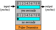
Device keeps outputting yes followed by no.
User defines the duration of yes and duration of no. |
INPUT:
yes = generate pulse
no = output no
OUTPUT:
yes = yes duration has not timed out
no = no duration has not timed out |
| Yes/No Switch |
 |
User sets switch to yes or no position to
indicate what the block will output. |
yes = switch is in yes position
no = switch is in no position |
| Error Detector |
 |
Device outputs a yes when an input of error
is recieved. Device outputs a no in all other situations. |
yes = input is error
no = input is yes or no |
|


