Lab 4 - The Datapath, and ALU Control Units
Intro:
For this lab you will be building the control units for a MIPS processor. There are two of them. The main control unit manages the datapath. It receives an opcode input from the currently executing instructions, and based on this opcode it configures the datapath accordingly. A truth table for the units functionality can be found in Figure 4.22 of your textbook. The figure is also shown below.

The second control unit manages the ALU. It receives an ALU opcode from the datapath controller, and the Funct Field from the current instruction. With these the ALU controller decides what operation the ALU is to perform. The following figures from your textbook give an idea of the inputs and outputs of the ALU controller.

The ALU Control Lines
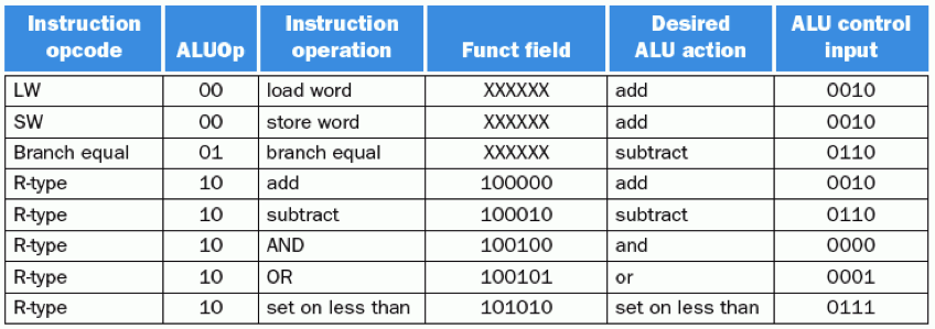
ALU Control Bits based on ALUop, and Funct filed

Truth Table for ALU Control
Deliverables
For this lab you are expected to build and test both the datapath and ALU control units. The target processor architecture will only support a subset of the MIPS instructions. These instructions are listed below. You only have to offer control for these instructions. Signal values can be found within your textbook.
- add, addu, addi
- sub, subi
- slt
- not, nor
- or
- and
- lw, sw
- beq
To complete this lab you are provided with the following skeleton code files. The control unit files should be familiar to you, but the library file may not be. This file is offered only to make your code more readable, and you are not obliged to use it. In the MIPS processor the opcode and funct values are assumed to be constants (Magic Numbers), and you can treat them as such. The library file is a way to assign global names to these value which can be used throughout your design. Examples of how to include the file is shown at the top of the control_unit, and alu_control files. The library is incomplete as written, and holds incorrect signal values
- Control Unit: control_unit.vhd
- ALU Control: alu_control.vhd
- Constants Library: cpu_constant_library.vhd
Architecture Case Study
For lab this week you are also expected to perform a simple case study. It is meant to show how important understanding a computer's architecture, and compiler is when developing efficient code. For this study you are to compare and analyze the execution time of the two programs given here. You should run a number of experiments varying the input size from 100, to 30,000.
Based on the results you are to write a report of your findings. The report should contain a graph of your data, and useful analysis of it. You should draw conclusions based on your findings. Reports that simply restate what is in the graph will not get full credit. The report should be in PDF format.
Turn-In:
Each group should turn in one tar file to iLearn. The contents of which should be:
- A README file with the group members names, and any incomplete or incorrect functionality
- A completed version of the control_unit.vhd, and alu_control.vhd files
- A completed version of of cpu_contant_library.vhd (only if used)
- A VHDL file(s) for the Testbenches
- A PDF report for your case study