Receiver Circuit and Display
The purpose of the receiver circuit is to display the conference room schedule for the current day and to receive any updated information from the transmitter. The information is displayed by rotating the text for each time slot across the LCD. The current time is always displayed on the left half of the LCD and the corresponding information is rotated across the right half. If the time slot is free, the text "EMPTY" is rotated.
The receiver circuit functions by constantly rotating the information on the LCD. Any time that it receives data a serial interrupt will occur. At this point, the circuit checks to see it has received one of two possible packet types. If it receives a BEGIN_TRANSMISSION, there is new data to store so it stops rotating text and starts storing data. If it receives a SAME_TRANSMISSION, the data hasn't changed. At this point there are two possibilities. If there was a transmission error on this time slot on a previous send, the data will be stored. If there was no error, then the data is exactly the same and doesn't need to be stored. This process is repeated for each time slot.
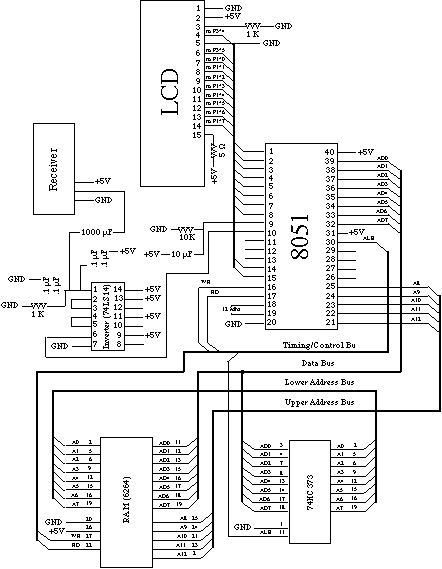
In order for data to be properly received, the signal must first be filtered before it can be sent to the processor. The receiver collects noise from the surroundings and this must be filtered out of the signal. Since the noise does not come in as strong as the intended signal, capacitors and inverters can be used to remove it. The signal is filtered through five capacitors and is then inverted three times (the signal sent is already inverted) before it is sent to the 8051. The exact value of the capacitors and the resistor may need to be varied based on different hardware combinations and board layouts.
External memory has also been added to our circuit because the 8051 only has 128 bytes of data memory and this design requires much more. This is necessary because storing data for an entire day can require up to 800 bytes. We are currently using 32k of RAM in case we change the amount of data that is stored for each day.
This circuit currently uses a sixteen character LCD display with back-lighting. With backlighting, the design uses approximately .2 amps. Without backlighting the design requires much less current.
All 8051 C code can be found here.
A complete parts list for the receiver circuit can be found here.
If the 8051 does not receive any data when the circuit is running, it may be because the receiver and the transmitter have not been tuned correctly. Tuning the receivers is the easiest way to correct this because changing the transmitter could affect other receiver circuits. Tuning can be done by attaching a logic analyzer to the pin on the 8051 that is used for receiving serial data. There is a variable capacitor on the receiver that needs to be adjusted until a good signal is shown on the logic analyzer. Only very small adjustments are usually required.