Parameterized System Design
Tony D. Givargis, Frank Vahid
Department of Computer Science and Engineering
University of California, Riverside, CA 92521
{givargis,
vahid}@cs.ucr.edu
Abstract
Continued growth in chip capacity has led to new methodologies stressing reuse, not only of pre-designed processing components, but even of entire pre-designed architectures. To be used across a variety of applications, such architectures must be heavily parameterized, so they can adapt to those applications' differing constraints by trading off power, performance and size. We describe several parameterized system design issues, and provide results showing how a single architecture with easily configurable parameters can support a wide range of tradeoffs.
Keywords
System-on-a-chip, low power, intellectual property, cache, on-chip bus, estimation, system parameters.
1. Introduction
The availability of large numbers of transistors on a chip has led to the growth of Intellectual Property (IP) based design of systems on a chip (SOC) [5]. Many IP-based design approaches focus on mixing-and-matching of diverse IP to build an application, representing a capture-and-simulate methodology. However, others focus on mapping an application onto a pre-designed complex SOC architecture built from existing IP [10][14][15][16] by configuring and extending that architecture, representing a configure-and-execute methodology [11]. Such a pre-designed architecture [17] consists of a microprocessor, memory hierarchy, direct memory access controller, and processor bus. A bridge to a peripheral bus connects to standard peripheral IP components (e.g., timers, counters, serial communication devices, network interfaces, etc.), as well as to a large programmable logic fabric and an off-chip bus. A programming, simulation and emulation environment supports the architecture. The architecture may be provided as HDL (hardware description language) source code, as an actual chip, or both. The large cost of developing such a complex architecture, environment, and possibly chip, is amortized over numerous applications. Due to the increasing gap between chip capacity and designer productivity [7], such amortization may be one of the only ways tomorrow's huge-capacity chips can actually be utilized.
Applications, especially those representing embedded systems, differ greatly in terms of their power, performance and size requirements. Though using the same basic architecture, applications may seek to minimize power, maximize performance, minimize size, or optimize some weighted combination of those constraints. Therefore, in order to maximize the number of applications that can use a pre-designed architecture, the architecture must be highly configurable.
Such configurability for a range of power, performance and size constraints requires a new focus on "parameterized system design," different from the past focus of building an architecture optimized for one particular set of constraints. The past focus was often transistor-centric, focusing on minimizing transistors under given power and performance constraints, or maximizing performance and minimizing power under given size constraints.
The recent attention of selecting the best cache parameters (size, associativity, etc.) for a specific application is a good example of the new parameterized focus [4][6]. We can introduce numerous parameters, incorporating numerous previously stand-alone techniques that tradeoff power, performance and size. Such techniques may involve caches, memory hierarchy, code compression, buses, buffer sizes, and so on.
The shift of focus, from minimizing transistors to maximizing configurability given the newfound abundance of transistors, can be compared to the shift of focus in the software field beginning two decades ago, given the then newfound abundance of program and data memory. The shift in software went from writing tight code to writing reusable software modules, first in the form of parameterized subroutines, and then in the form of parameterized objects.
This paper represents an attempt to describe the newly emerging field of parameterized system design. We provide an example of a parameterized system and describe numerous likely system parameters. We provide definitions of several types of parameters. We describe interdependencies among parameters. We describe the system design problem of searching for the best parameter configuration and describe the parameter interdependency problem in this context. We also provide some early results demonstrating how a single parameterized system can lead to implementations with a large range of power and performance characteristics.
2. Parameterized architecture example
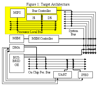
To most directly present the idea of parameterized system design, we begin by describing our example parameterized system-on-a-chip architecture, shown in Figure 1. A MIPS R2000 processor and instruction and data caches communicate over a high-speed processor-local bus. The on-chip memory and direct memory access (DMA) controller cores are connected to the system bus, which in turn is bridged to the processor-local bus via a bus controller. Universal Asynchronous Receiver and Transmitter (UART) and JPEG decoder cores are connected to the peripheral bus, which is bridged to the system bus. Both the UART and JPEG decoder cores are DMA capable. The DMA controller is capable of transferring data between peripheral cores and memory without the intervention of the processor. The processor can run concurrent to the DMA until a cache miss occurs, at which point the processor is blocked waiting for the DMA transfer to complete. Most cores in our architecture are parameterizable. These parameters will be discussed next.
The MIPS R2000 processor can be instantiated with code compression enabled or disabled, and local instruction cache size set to one of 1, 4, 16 or 32. Processor local, system, and on-chip peripheral buses of our architecture can each be instantiated with varying data/address bus-width and encoding schemes. Bus widths can be set to one of 4, 8, 16 or 32. Data/address encoding can be set to binary (no encoding) or bus-invert [8]. The total size, block-size (line) and associativity of the instruction and data caches can also vary. Cache size can be set to a value in the range of 128 to 64K bytes, block-size can be set to one of 4, 8, 16, or 32 and associativity can be set to one of 1, 2, 4, or 8. The on-chip memory can be instantiated with 4K to 256K bytes of storage. In addition to selecting DMA priorities, the DMA controller can be instantiated with maximum block transfer size set to one of 4, 16, 64 or 128 bytes. The UART core�s transmitter/receiver buffer sizes can each be set to one of 1, 2, 4, 8, or 16 bytes. Finally, the JPEG decoder core�s pixel resolution can be set to one of 10 or 12 bits.
3. Parameter definitions
We define an SOC parameter as a feature that can be modified to tradeoff an application's power, performance and/or size metrics, without affecting the application's essential functionality. Each parameter may be set to one of a finite number of values. A configuration is a selection of values for all parameters of an SOC.
3.1 Static versus dynamic parameters
The two main types of SOC parameters are static and dynamic. A static parameter is a parameter whose value must be set before we fabricate an instance of the SOC. This value is therefore fixed in the fabricated SOC. The parameter typically appears in the HDL source used to eventually create an instance of the SOC. The source may be behavioral or structural. The parameter often appears as a generic in a HDL, such as a buffer-size generic for a UART. More complex parameters may not be representable by generics, but rather may require new HDL code to be generated for each parameter value, such as a parameter indicating ROM size to a ROM generator.
A dynamic parameter, in contrast, is one whose value may be set in an already fabricated SOC. The SOC therefore will contain extra on-chip structure able to support various parameter settings. The parameter typically appears as part of the SOC design, such as a register whose value may result in disabling portions of a UART buffer. Dynamic parameters are therefore run-time configurable. They are typically configured by software, but may also be configured by other hardware or by setting external pins. The existence of dynamic parameters brings about the concept of a logical architecture. Each configuration of a parameterized SOC architecture represents a single logical architecture.
A dynamic parameter's run-time configurability introduces the notion of configurability granularity, which is the time slice after which this parameter can or should be reconfigured. Examples of fine-grained configurable dynamic parameters are those that are reconfigured for every application code segment, every task context switch, or every cache hit/miss. Example of coarse-grained configurable dynamic parameters are those that are reconfigured on power up, at the start of an application, when battery power is low, or through user commands.
Static parameters can be converted to dynamic ones through a process of architectural redesign. For example, a static buffer-size parameter can be made dynamic by creating a buffer of the maximum size possible, and adding an additional register indicating the current value of the parameter. This register's output would be used to enable/disable registers in the buffer, and to set the signal indicating a full buffer when all enabled registers were being used.
Likewise, dynamic parameters can be converted to static ones. For example, the dynamic buffer-size parameter above can be converted to a static parameter by removing the size register, and creating instead a buffer of exactly the desired size. As another example, parameters typically thought of as software configurable parameters (e.g., DMA block size) could be converted to static parameters by hardwiring the value for a particular application.
3.2 Abstraction level
Parameters can also be classified by their level of abstraction, independent of whether they are static or dynamic. We distinguish among three levels - circuit, architecture, and application.
Circuit-level parameters, when set, keep the same general logical architecture, but make small modifications to the way bits are stored or transferred. Examples of such parameters include parity, bus-invert encoding or other encoding, code compression, and buffer sizes.
Architecture-level parameters can reconfigure the system to very different logical architectures, changing for example the system's bus hierarchy, memory hierarchy, or physical communication link.
Application-level parameters actually change the system's functionality in a non-essential way, typically impacting quality features. An example is a pixel resolution parameter in a picture processing application, which results in lower-quality video but less power. Another example is a sorting algorithm parameter, which trades off memory requirements with speed.
An analogy may be made with the various layers known in networking.
4. Parameter interdependency
Most system parameters are interdependent on each other. These interdependencies must be considered when selecting a valid configuration, i.e., assignment of values to all parameters. Interdependencies can be classified as either performance related or hard, i.e., constraint related, interdependencies.
Performance related dependencies between a pair of parameters dictate that values for these parameters must be selected simultaneously in order to achieve overall optimal solutions. Likewise, such dependency dictates that selecting the optimal value for one parameter followed by selecting the optimal value for the other may result in an inferior solution. As an example, it has been shown that cache and bus parameters bear a strong performance dependency [2].
Hard or constraint related dependencies are those dependencies that must be considered in order to select valid configurations. As an example, given our target architecture, increasing the UART�s transmitter buffer size past the DMA�s block transfer size would not be valid. Likewise, decreasing the size of the on-chip-memory to less than the size of a cache block will also result in a faulty architecture.
It must be noted that while performance related interdependencies make the parameter exploration slow, by exponentially enlarging the design space, hard and constraint related interdependencies make such exploration faster by pruning the design space. However, for a given architecture, it is crucial to discover all dependencies among parameters in order to construct efficient and accurate design exploration tools.
5. Evaluation dependency
In order to select optimal parameter values, i.e., a good configuration, it is essential to evaluate various performance metrics, such as power, execution time and area. In this section we will describe three simulation-based approaches for evaluating such metrics. Furthermore, we point out the dependency of parameters on one another and how this dependency must be taken into consideration in order to perform fast and accurate evaluation of performance metrics.
Our first approach is based on a full simulation of an application. Here a parametrizable high-level model of the architecture is developed. Then, for each configuration, a full simulation is performed and metrics are gathered. This process is iterated until a desired configuration is obtained. This approach is simple but slow because it assumes that all parameters are dependent on one another. For example, when evaluating power, changing the value of the UART buffer size, may not effect the power consumption contributed by the MIPS and cache sub-system, thus one does not need to re-simulate these components.
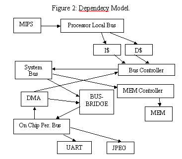
Our second approach, trace-driven simulation, takes advantage of such dependencies (or lack of). This approach also requires a parametrizable high-level model of the architecture. When the system is simulated for some configuration, in addition to outputting performance metrics, each core generates some intermediate data, i.e., a trace of its input/output data that is subsequently used by the trace-simulators. Trace-simulators are partial simulators that process the input trace and report performance metrics. When iterating, a dependency model can be used to determine when traces can be used in place of full simulation. A dependency model can be depicted as a graph with nodes representing cores and arrows representing the dependencies. The dependency model for our target architecture is given in Figure 2.
Our third approach improves upon our second approach by replacing some of the trace simulators1 with analytical or statistical models that further speedup evaluation of performance metrics, with only small losses in accuracy. For example, assuming random data transmission over a bus, and knowing the traffic on it (obtained from the trace, say) one can use equations to determine the bit-switching activity and compute power consumption of that bus. Likewise, after simulating a cache for a small number of configurations, one can use curve fitting to estimate cache performance metrics for other configurations.
6. Experiments
In this section, we will outline our experimental setup and give some results. Our goal is to demonstrate the large tradeoff between power and execution time when system parameters are varied.
For our experiments, we have used the presented architecture to implement a serial JPEG accelerator. In our application, the UART is used as a high-speed link between a host (off-chip) processor and our accelerator. Compressed JPEG images are received via the UART and transferred to the on-chip memory using DMA. Then, Huffman decoding is performed using the on-chip MIPS processor. Next, the decoded image is transferred, one 8x8-pixel block at a time, to the JPEG decoder using DMA. The JPEG decoder performs de-quantization and applies the inverse discrete cosine transform to each block and transfers (using DMA) the block back to memory. Finally, the resulting image is sent back, as they become available, to the host (off-chip) processor.
We have implemented an executable C++ object-oriented model of the architecture presented in Figure 1. In our model, all computational, e.g., UART, communication, e.g., busses, and storage, e.g., caches, are represented as objects. Furthermore, computational cores are designed as active object, i.e., capable of executing in their own thread of execution and communication objects are designed to facilitate synchronous message passing between various threads of execution. The high-level model, currently 12,000 lines of code, can be compiled and executed on a workstation.
Prior to execution of the system model, the software running on the MIPS, e.g., the software for the serial JPEG accelerator application, is compiled separately using a C compiler and loaded into the on-chip memory. Also, the various system parameters are set and the model is executed. The following parameters are varied in our experiments: cache sizes (128, 8K, or 64K), cache line (4 or 16), cache associativity (1 or 8), processor, system and peripheral bus data width (4 or 32), bus data encoding (binary or bus-invert), JPEG decoder pixel resolution (10 or 12 bits), and UART transmit buffer size (1 or 16). Input to the UART is emulated to be a 640 by 480 pixel color photograph in JPEG format. When the execution completes, the model outputs the performance, i.e., power consumption and execution time, of the overall system. In our previous work, we have shown that our simulation model is on the average accurate to 85% when compared to gate-level simulation results. A detailed discussion of our simulation model and various power and performance evaluation techniques can be found in [3][12]. Considering the large design space of our architecture (approximately trillions of configurations), the advantage of using a high-level simulation model is its speed of execution, enabling wider exploration. For our serial JPEG accelerator application, we were able to simulate 100 configurations per minute on a 450MHz machine. In comparison, gate-level simulation would have required several days per configuration.
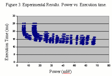
For our experiments we selected a total of 9016 configurations that represented the extremes and median values for each parameter described in earlier sections. The power and execution time are depicted in Figure 3. Results show a significant tradeoff between power and execution time, with a 2x range for execution time and a 10x range for power.
7. Conclusions
We showed that a few relatively straightforward static system parameters could yield a power/performance tradeoffs with a range of 10x. Our system architecture could have been much more heavily parameterized, leading to an even bigger tradeoff potential. Such parameters could be created from existing and future low-power techniques. For example, the microprocessor could have had a parameterized datapath that could vary from 8 to 32 bits. The buses could have used more powerful encoding, such as T0 for address [1] or limited-weight codes for data [9]. We could have used code compression. Furthermore, a parameter-aware compiler could be used to optimize an application for a particular configuration [13]. These possibilities imply that we may be able achieve tradeoffs with ranges of 100x or even 1000x, making parameterized systems widely applicable and hence making further focus on parameterized system design important.
8. References
[1] W. Fornaciari, D. Sciuto, C. Silvano. Power Estimation for Architectural Explorations of HW/SW Communication on System-Level Buses. International Workshop on Hardware/Software Codesign, 1999.
[2] T.D. Givargis, J. Henkel, and F. Vahid. Interface and Cache Power Exploration for Core--Based Embedded System Design. International Conference on Computer Aided Design, 1999.
[3] T.D. Givargis, F. Vahid, J. Henkel. A Hybrid approach for Core-based System-level Power Modeling. Asia and South Pacific Design Automation Conference, 2000.
[4] R. Gupta and Y. Zorian. Introducing Core-Based System Design. IEEE Design & Test, Vol. 14, No. 4, Oct-Dec 1997, pp. 15-25.
[5] K. Kiefendorff. Transistor Budgets Go Ballistic. Microprocessor Report, Volume 12, Number 10, August 3, 1998, 14-18.
[6] Y. Li and J. Henkel. A Framework for Estimating and Minimizing Energy Dissipation of Embedded HW/SW Systems. Design Automation Conference, pp.188-193, 1998.
[7] Semiconductor Industry Association Roadmap 1997, http://notes.sematech.org/ntrs/PublNTRS.nsf.
[8] M.R. Stan, W.P. Burleson. Bus-Invert Coding for Low Power I/O. IEEE Transactions on VLSI, March 1995.
[9] M.R. Stan, W.P Burleson. Coding a Terminated Bus for Low Power. Great Lakes Symposium on VLSI, March 1995.
[10] B. Payne. Rapid Silicon Prototyping: Paradigm for Custom System-on-a-Chip Design. http://www.vlsi.com/velocity, 1998.
[11] F. Vahid, T.D. Givargis, The Case for a Configure-and-Execute Paradigm. International Workshop on Hardware/Software Codesign, 1999.
[12] F. Vahid, T.D. Givargis. Incorporating Cores into System-Level Specification. International Symposium on System Synthesis, 1998.
[13] A.V. Veidenbaum, W. Tang, R. Gupta, A. Nicolau, X. Ji. Adapting Cache Line Size to Application Behavior. International Conference on Supercomputing, 1999.
[14] P. van der Wolf, P. Lieverse, M. Goel, D.L. Hei, K. Vissers. An MPEG-2 Decoder Case Study as a Driver for a System Level Design Methodology, pp. 33-37, International Workshop on Hardware/Software Codesign, 1999.
[15] J. Van Meerbergen, A. Timmer, J. Leijten, F. Harmsze, M. Strik. Experiences with System Level Design for Consumer ICs, VLSI'98, pp 17-22.
[16] Velocity product information, VLSI Technology Inc. http://www.vlsi.com/velocity.
[17] Virtual Socket Interface Association, Architecture Document. http://www.vsi.org, 1997.
| 1 | Trace-simulators often are partial simulator, i.e., they don't completely implement that behavior of a core, and thus they run faster. As an example, trace-simulators are often used to evaluate cache performance given a trace of memeory references. return to text. |